
Utilization device for pressure energy of gas well of natural gas

A technology of pressure energy and natural gas, applied in gas/liquid distribution and storage, pipeline system, mechanical equipment, etc., can solve the problem of lack of pressurization effect, weakened injection pressurization effect of fixed ejector, and inability to adapt to natural gas. Changes in pressure and flow, etc., to achieve the effect of efficient utilization

Inactive Publication Date: 2018-10-16
CHINA PETROLEUM & CHEM CORP +1
View PDF6 Cites 6 Cited by
  • Summary
  • Abstract
  • Description
  • Claims
  • Application Information

AI Technical Summary

Problems solved by technology

[0005] However, the existing ejectors all adopt a fixed structure, and the structure of the nozzle and diffuser is set according to the initial parameters of the work, which cannot adapt to changes in the pressure and flow of natural gas
As the development of the gas field enters the middle and later stages, the wellhead pressure of the gas well decreases rapidly, which causes the boosting effect of the fixed ejector to significantly weaken, or even fail to achieve the boosting effect

Method used


Image

  • Utilization device for pressure energy of gas well of natural gas
  • Utilization device for pressure energy of gas well of natural gas

Examples


Embodiment 1

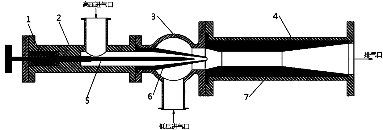
[0052] figure 1 A schematic structural diagram of a natural gas well pressure energy utilization device according to an exemplary embodiment of the present invention is shown.

[0053] The natural gas well pressure energy utilization device according to an exemplary embodiment of the present invention includes:

[0054] a mixing chamber, the mixing chamber communicates with the high-pressure intake pipe 2, the low-pressure intake pipe 3 and the mixed medium-pressure exhaust pipe 4;

[0055] Ejector, ejector includes: adjustable cone 5, adjustable cone 5 is connected with high-pressure inlet pipe 2 through threads, and uses sealing packing 1 to seal high-pressure gas; nozzle 6, nozzle 6 is arranged on high-pressure inlet pipe 2 and Inside the low-pressure intake pipe 3, the nozzle 6 is overlaid on the lower part of the adjustable cone 5, and the nozzle 6 is fixed by the flanges of the high-pressure intake pipe 2 and the low-pressure intake pipe 3;

[0056] The mixing diffuser...


PUM

PropertyMeasurementUnit
Tube chiefaaaaaaaaaa

Abstract

The invention discloses a utilization device for pressure energy of a gas well of natural gas. The device comprises a high-pressure gas inlet pipe, a low-pressure gas inlet pipe, a mixed medium-pressure gas exhaust pipe, a mixing chamber, an ejector, a nozzle and a mixed pressure diffusion pipe; the high-pressure gas inlet pipe is arranged perpendicular to the low-pressure gas inlet pipe, the mixed medium-pressure gas exhaust pipe is arranged parallel and opposite to the high-pressure gas inlet pipe, and the mixed medium-pressure gas exhaust pipe and the high-pressure gas inlet pipe are connected perpendicular to the low-pressure gas inlet pipe; the mixing chamber is a space formed by communicating of the high-pressure gas inlet pipe, the low-pressure gas inlet pipe and the mixed medium-pressure gas exhaust pipe; the ejector comprises an adjustable cone, wherein the adjustable cone is arranged in the high-pressure gas inlet pipe; the nozzle is arranged inside the high-pressure gas inlet pipe and the low-pressure gas inlet pipe, and the nozzle externally sleeves the lower portion of the adjustable cone; and the mixed pressure diffusion pipe is arranged in the mixed medium-pressure gas exhaust pipe. The device has the advantages that through the adjustable natural gas ejector pressurizing structure, during pressure change of the gas well, the ejector structure is adjusted to maximally utilize the pressure energy of the high-pressure natural gas well so as to pressurize the low-pressure natural gas well.

Description

technical field [0001] The invention relates to the field of natural gas development, in particular to a device for utilizing pressure energy of natural gas wells. Background technique [0002] In the process of natural gas exploitation, due to the different development layers and development time of each gas well in the gas field, there will be high-pressure gas wells and low-pressure gas wells in the same gas field at the same development stage (especially in the middle and late stages of development). In order to meet the requirements of the export pipeline, high-pressure gas needs to be throttled and depressurized, resulting in a huge waste of natural gas pressure energy; while the pressure of low-pressure gas is lower than the pressure of the export pipeline network, it cannot enter the pipeline network, and it needs to be pressurized to achieve export, increasing power consumption. [0003] At present, devices that use gas pressure to pressurize natural gas include ex...

Claims


Application Information

Patent Timeline
IPC IPC(8): F17D1/065F17D3/01
CPCF17D1/065F17D3/01
Inventor 黄辉李奇李伟郑友林
Owner CHINA PETROLEUM & CHEM CORP
Learn More