


Quick Research
Generate reliable direction feasibility study reports for your R&D in just a few steps.

Technical Q&A
Discover and master advanced knowledge NOW. Basics, ideas, possibilities, all at once.

Find Solutions
As an expert in R&D theories, this can generate solutions to your technical problems instantly.

Evaluate Feasibility
Analyze your overall solution with one click, know your potential R&D risks in advance.

Monitor Landscape
Get weekly tech updates, stay abreast of the latest tech innovations and key insights.
Novel coiled material tail end positioning and conveying device
A technology for conveying devices and coils, which is applied in the direction of conveyor control devices, conveyors, conveyor objects, etc., and can solve problems such as coil deformation, affecting the quality of coil products, and inability to adjust coil specifications.
- Summary
- Abstract
- Description
- Claims
- Application Information
AI Technical Summary
Problems solved by technology
Method used
Image

Examples
Embodiment 1
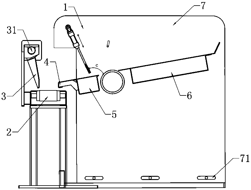
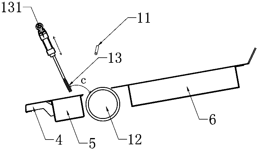
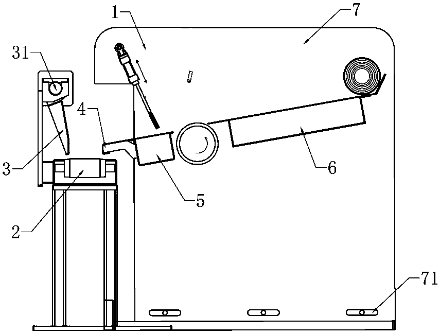
[0030] See 1 and attached figure 2 As shown, in this embodiment, a new coil tail end directional conveying device includes a conveying channel 2 (a conveying belt in this embodiment) for accepting and conveying the coiled material 10 and a homing device located upstream of the conveying channel 2. Tail positioning mechanism 1, wherein the tail positioning mechanism 1 includes a detection unit 11 for sensing the tail end orientation of the coil 10, an orientation roller 12 for rotating and adjusting the tail end orientation of the coil 10 (as shown in the accompanying drawings, The directional roller 12 of this embodiment rotates counterclockwise) and the positioning assembly 13 located on the downstream side of the directional roller 12 is adjusted to the preset first position by using the tail-seeking positioning mechanism 1 to rotate the tail end of the coil 10, so that The coiled material 10 rolls away from the tail-seeking positioning mechanism 1 and stops on the conveyin...
Embodiment 2
[0050] See attached Figure 9 And attached Figure 10 As shown, the difference between this embodiment and the first embodiment is that the positioning assembly 13 of this embodiment is a reciprocating positioning roller, wherein the coil 10 for rotating and adjusting is in contact with the surface of the positioning roller. Thereby, the outer peripheral surface of the coil 10 is in contact with the roller surfaces of the positioning roller and the orientation roller 12 respectively, and a predetermined rotation angle c is formed between the two contact positions formed (the rotation angle here is determined by the positioning in the actual assembly. determined by the position of the roller).
[0051] In addition, the positioning roller of this embodiment can be driven without power, and only conflicts with the coiled material 10. In this way, when the coiled material 10 is rotated and adjusted with the orientation roller 12, there is a distance between the roll surface of th...
Embodiment 3
[0055] See attached Figure 11 And attached Figure 12 As shown, the difference between this embodiment and the first embodiment is that the positioning assembly 13 is a positioning guide plate used to communicate with the conveying channel 2 and the tail-seeking positioning mechanism 1, wherein the positioning guide plate takes its front end as the axis 132 swings back and forth, when the positioning guide plate swings to a predetermined position to stop the coiled material 10 rolling to the orientation roller 12 place, that is, the positioning guide plate swings and rolls to the coiled material 10 at the orientation roller 12 place. The coiled material 10 subjected to the blocking effect is rotated and adjusted with the orientation roller 12; when the predetermined position of the hem of the positioning guide plate is to avoid the rolling path of the coiled material 10 and allow the coiled material 10 to roll onto the conveying channel 2 along its surface, that is, the posit...
PUM
 Abstract
Description
Claims
Application Information
 - R&D Engineer
- R&D Manager
- IP Professional
- Industry Leading Data Capabilities
- Powerful AI technology
- Patent DNA Extraction
Browse by: Latest US Patents, China's latest patents, Technical Efficacy Thesaurus, Application Domain, Technology Topic, Popular Technical Reports.
© 2024 PatSnap. All rights reserved.Legal|Privacy policy|Modern Slavery Act Transparency Statement|Sitemap|About US| Contact US: help@patsnap.com