
Five-axis numerical control machine tool space error distinguishing method

A space error, CNC machine tool technology, applied to metal processing machinery parts, measuring/indicating equipment, metal processing equipment, etc., can solve problems such as interference errors, unfavorable macro programming, unfavorable automatic compensation, etc.

Inactive Publication Date: 2018-10-16
TIANJIN SINO GERMAN VOCATIONAL TECHNICAL COLLEGE
View PDF3 Cites 13 Cited by
  • Summary
  • Abstract
  • Description
  • Claims
  • Application Information

AI Technical Summary

Problems solved by technology

By adjusting the length of the ballbar and the height of the center seat, after running the program, and then according to the corresponding algorithm, the error elements in the XOY plane can be obtained; this method is mostly used for the measurement of three-axis machine tools, and for five-axis machine tools by its It is the poor applicability of machine tool error measurement for surface processing;
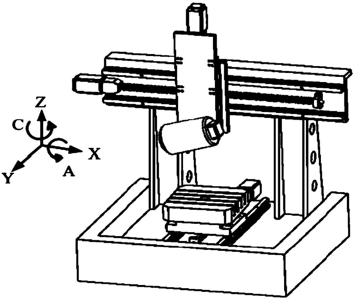
[0003] For five-axis CNC machine tools, there are a lot of coupling phenomena in multi-axis interpolation, and the spatial errors mainly include the linear error of the feed axis and the rotation error of the rotary axis; most of the original identification methods use changing the installation height of the ballbar Based on the ballbar length method, this method is easy to add interference errors in the adjustment process, resulting in inaccurate solution results; at the same time, the traditional method needs to dismantle the ballbar multiple times, because it is difficult to disassemble and install in the same process. On the coordinate basis, the resulting data is poorly referable. Moreover, the process of disassembly and reinstallation takes a long time, which is not conducive to automatic compensation, especially not conducive to the later research of machine learning and macro programming.

Method used


Image

  • Five-axis numerical control machine tool space error distinguishing method
  • Five-axis numerical control machine tool space error distinguishing method
  • Five-axis numerical control machine tool space error distinguishing method

Examples


Embodiment Construction

[0038] Below in conjunction with specific embodiment, the technical scheme of this patent is described in further detail;

[0039] A method for identifying spatial errors of a five-axis numerically controlled machine tool, comprising the following steps:

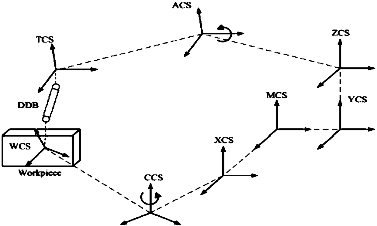
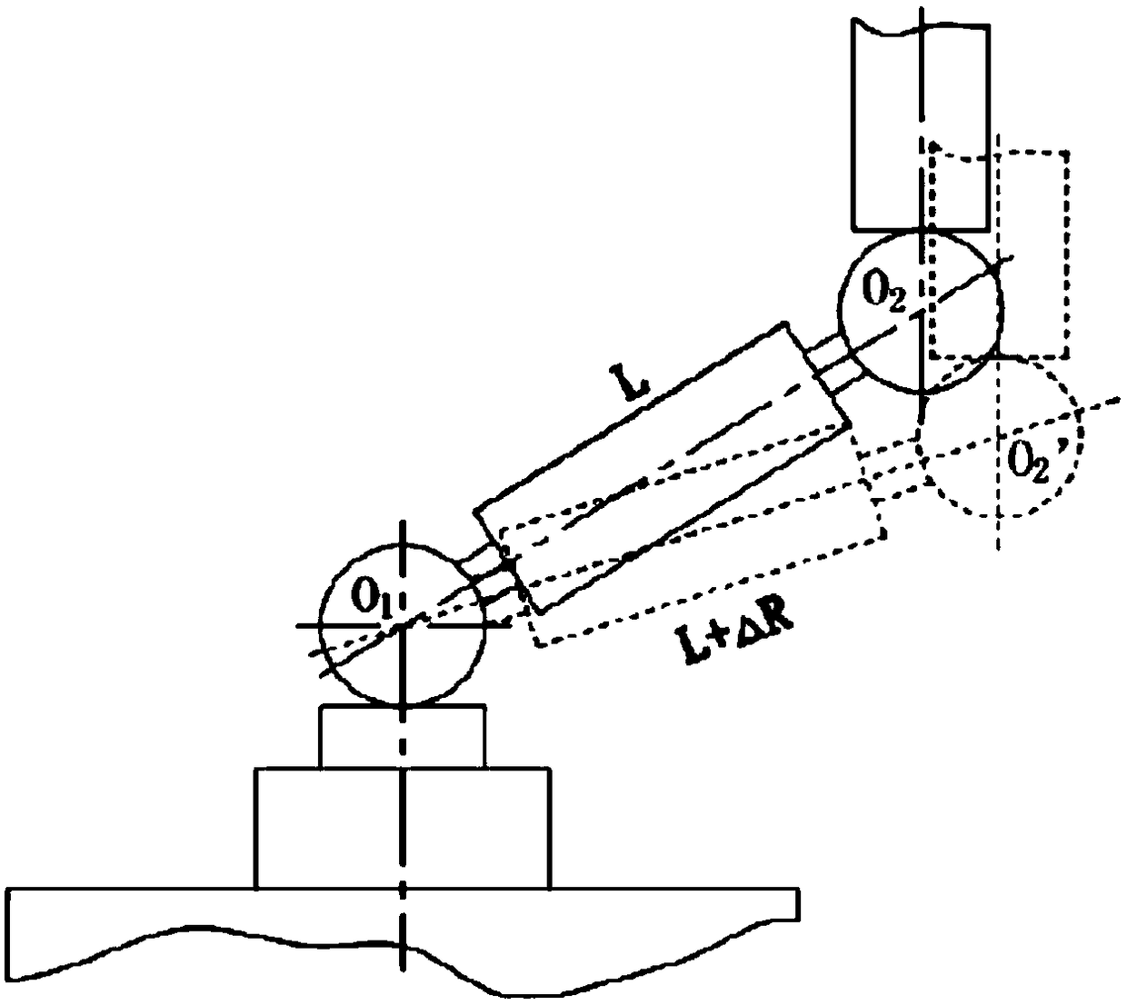
[0040] Step 1. Build a ballbar error measurement device with one end fixed on the spindle of the five-axis CNC machine tool and the other end fixed on the center of the rotary table; the ballbar center ball 2 is connected to the spindle through the tool cup 1, and the ballbar sensor ball 5 The sensor ball 5 can measure the real-time length of the ballbar in real time by connecting the center cup 6 with the center seat 7 at the center of the turntable.

[0041] Step 2. Establish a spatial error measurement model according to the ballbar measuring device;

[0042] Step 3. Establish a model experiment, read the theoretical rod length of the ballbar of the CNC lathe and the actual rod length displayed by the ballbar through the...


PUM


Abstract

The invention belongs to the field of numerical control machine tool measurement technology study and particularly relates to a five-axis numerical control machine tool space error distinguishing method. According to the method, a ball bar instrument error measuring device with one end fixed to a main shaft of a five-axis numerical control machine tool and the other end fixed to the center of a rotating working table is put up; a space error measuring model is set up; a model test is set up, by means of compensation work at different angles of a ball bar instrument, the theory bar length of the ball bar instrument of the numerical control machine tool and the actual bar length displayed by the ball bar instrument are read, data is taken into the space error measuring model, the angle errorfactor and the rotating error factor of a rotating shaft of the five-axis numerical control machine tool are distinguished, the ball bar instrument is changed from XOY single plane motion into spacemulti-plane motion, and the distinguishing range of the ball bar instrument is converted from plane rotation into space rotation.

Description

technical field [0001] The invention belongs to the research field of numerical control machine tool measurement technology, and relates to a five-axis numerical control machine tool space error identification method. Background technique [0002] The original error identification method of CNC machine tools is to install one end of the ballbar in the tool cup and the other end on the center seat. By adjusting the length of the ballbar and the height of the center seat, after running the program, and then according to the corresponding algorithm, the error elements in the XOY plane can be obtained; this method is mostly used for the measurement of three-axis machine tools, and for five-axis machine tools by its It is the poor applicability of machine tool error measurement for surface processing; [0003] For five-axis CNC machine tools, there are a lot of coupling phenomena in multi-axis interpolation, and the spatial errors mainly include the linear error of the feed axis...

Claims


Application Information

Patent Timeline
IPC IPC(8): B23Q17/24
CPCB23Q17/24B23Q17/2495
Inventor 李巍左维骆鸣孟祥懿李文马林旭杜慧起毕彦龚勋
Owner TIANJIN SINO GERMAN VOCATIONAL TECHNICAL COLLEGE
Learn More