
Iron barrel paint spraying device for environmental protection machinery

A technology of machinery and iron barrels, which is applied in the field of iron barrel paint spraying devices for environmental protection machinery, which can solve the problems of uneven, difficult, and troublesome spraying of paint, and achieve the effects of uniform spraying, strong practicability, and improved painting efficiency

Inactive Publication Date: 2018-10-16
彭翠芳
View PDF0 Cites 29 Cited by
  • Summary
  • Abstract
  • Description
  • Claims
  • Application Information

AI Technical Summary

Problems solved by technology

[0002] In recent years, with the rapid development of China's economy and technology, the iron barrel manufacturing technology has also developed rapidly. From the aspects of products, processes, materials, equipment, environmental protection and theoretical research, in the process of making barrels, in order to avoid Rust, need to paint the formed barrel, usually manually, the painting is more troublesome, and the paint is uneven, especially the painting process on the inner wall of the barrel is more difficult, the production efficiency of the factory is not very high, Therefore, in response to the above problems, we proposed an iron barrel paint spraying device for environmental protection machinery

Method used


Image

  • Iron barrel paint spraying device for environmental protection machinery
  • Iron barrel paint spraying device for environmental protection machinery
  • Iron barrel paint spraying device for environmental protection machinery

Examples


Embodiment Construction

[0026] In order to make the object, technical solution and advantages of the present invention clearer, the present invention will be further described in detail below in conjunction with the accompanying drawings and embodiments. It should be understood that the specific embodiments described here are only used to explain the present invention, not to limit the present invention.

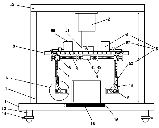
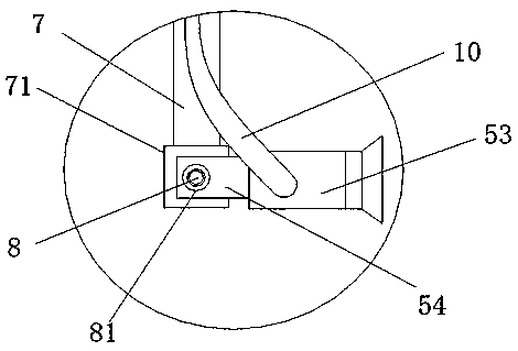
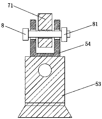
[0027] Such as figure 1 , figure 2 and image 3 The shown a kind of environmental protection machine is used the iron barrel paint spraying device, comprises base 1, rotating motor 2, mounting plate 3, adjusting device 4 and paint spraying device 5, and the upper end of described base 1 is symmetrically fixedly provided with column 11, and two described A horizontal plate 12 is welded between the upper ends of the columns 11, the rotating motor 2 is fixedly arranged in the center of the lower end surface of the horizontal plate 12 through the mounting base, the output shaft of the rotating motor...


PUM


Abstract

The invention discloses an iron barrel paint spraying device for environmental protection machinery. The iron barrel paint spraying device comprises a base, a rotating motor, a mounting plate, an adjusting device and paint spraying devices. The rotating motor is arranged on the lower end face of a transverse plate, and the end of an output shaft of the rotating motor is fixedly arranged at the upper end of the mounting plate. The adjusting device comprises a double-shaft motor and two screw rods, sliding blocks are arranged on the screw rods, electronic telescopic rods are arranged at the lower ends of the sliding blocks, and the two paint spraying devices are symmetrically arranged on two sides of the mounting plate. Each paint spraying device comprises a paint barrel, a pump body and a paint spraying head, wherein the paint spraying head is hinged to the lower end of the corresponding electronic telescopic rod, and an inlet and an outlet of the pump body are connected with the paintbarrel and the paint spraying head separately. According to the diameter of an iron barrel, the positions of the paint spraying devices can be adjusted from two sides, the directions of the spraying heads can be adjusted, and thus paint spraying can be conveniently carried out on the outer wall and the inner wall of a barrel body; in combination with the rotating motor and the telescopic rods, therequirement for different-depth paint spraying on the interior and exterior of the barrel body can be met; and rotatable paint spraying is adopted, so that uniformity and practicality are higher.

Description

technical field [0001] The invention relates to the technical field of environmental protection machinery, in particular to an iron barrel paint spraying device for environmental protection machinery. Background technique [0002] In recent years, with the rapid development of China's economy and technology, the iron barrel manufacturing technology has also developed rapidly. From the aspects of products, processes, materials, equipment, environmental protection and theoretical research, in the process of making barrels, in order to avoid Rust, need to paint the formed barrel, usually manually, the painting is more troublesome, and the paint is uneven, especially the painting process on the inner wall of the barrel is more difficult, the production efficiency of the factory is not very high, So in view of the above problems, we have proposed a paint spraying device for environmental protection machinery with iron barrels. Contents of the invention [0003] (1) Technical p...

Claims


Application Information

Patent Timeline
IPC IPC(8): B05B13/04B05B13/06B05B13/02B05B15/68
CPCB05B13/0421B05B13/0285B05B13/0636B05B15/68
Inventor 彭翠芳
Owner 彭翠芳
Learn More