
PTZ camera field calibration and focus fixing method

An on-site calibration and camera technology, which is applied in image enhancement, image analysis, image data processing, etc., can solve problems such as uneven processing accuracy and inability to solve PTZ camera parameter calibration, and achieve effective distortion and reduce calibration workload.

Active Publication Date: 2018-10-12
BEIHANG UNIV
View PDF1 Cites 15 Cited by
  • Summary
  • Abstract
  • Description
  • Claims
  • Application Information

AI Technical Summary

Problems solved by technology

However, the above method is mainly suitable for camera calibration when the focal length is fixed, and still cannot solve the parameter calibration problem of PTZ cameras with continuously changing focal length
[0005] Aiming at the problem of PTZ surveillance camera calibration, many calibration methods have been proposed in the prior art. For example, Sinha and Polleveys proposed a method for discrete sampling calibration of PTZ camera zoom parameters (reference [1] SinhaS N and Polleveys M.Pan -tilt-zoom Camera Calibration and High-resolutionMosaic Generation.Computer Vision and Image Understanding.2006,103(3):170-183P); Sarkis and others proposed a method of using moving least squares to establish the camera internal parameter function (reference [ 2] Sarkis M, Senft C and Diepold K.Calibrating an Automatic Zoom Camera With Moving Least Squares.IEEE Transactions on Automation Science and Engineering.2009,6(3):492-503P); Ashraf and Foroosh et al proposed to use non-overlapping field of view PTZ camera self-calibration method (reference [3] Ashraf N and Foroosh H.Robust Auto-calibration of aPTZ Camera with Non-overlapping FOV.In International Conference on Pattern Recognition,Dec.2008:738-748P), in these known Among the methods, some ignore lens distortion, some assume that the change of lens distortion is a linear change with magnification, and some assume that lens distortion satisfies the distortion model. However, for lenses with uneven processing accuracy, lens distortion cannot Described by a simple distortion model

Method used


Image

  • PTZ camera field calibration and focus fixing method
  • PTZ camera field calibration and focus fixing method
  • PTZ camera field calibration and focus fixing method

Examples


Embodiment Construction

[0022] The present invention will be further described in detail with reference to the accompanying drawings and embodiments.

[0023] In the existing PTZ camera self-calibration method, a polynomial distortion model is used to fit the lens distortion, but for a non-strictly axisymmetric lens, a simple distortion model cannot be used to fit it. In order to solve this problem, the present invention proposes a PTZ camera on-site calibration and focusing method, which can automatically calculate the internal reference matrix of the distorted image and the distortion correction parameters of each pixel, and realize high-precision and automatic correction of lens distortion.

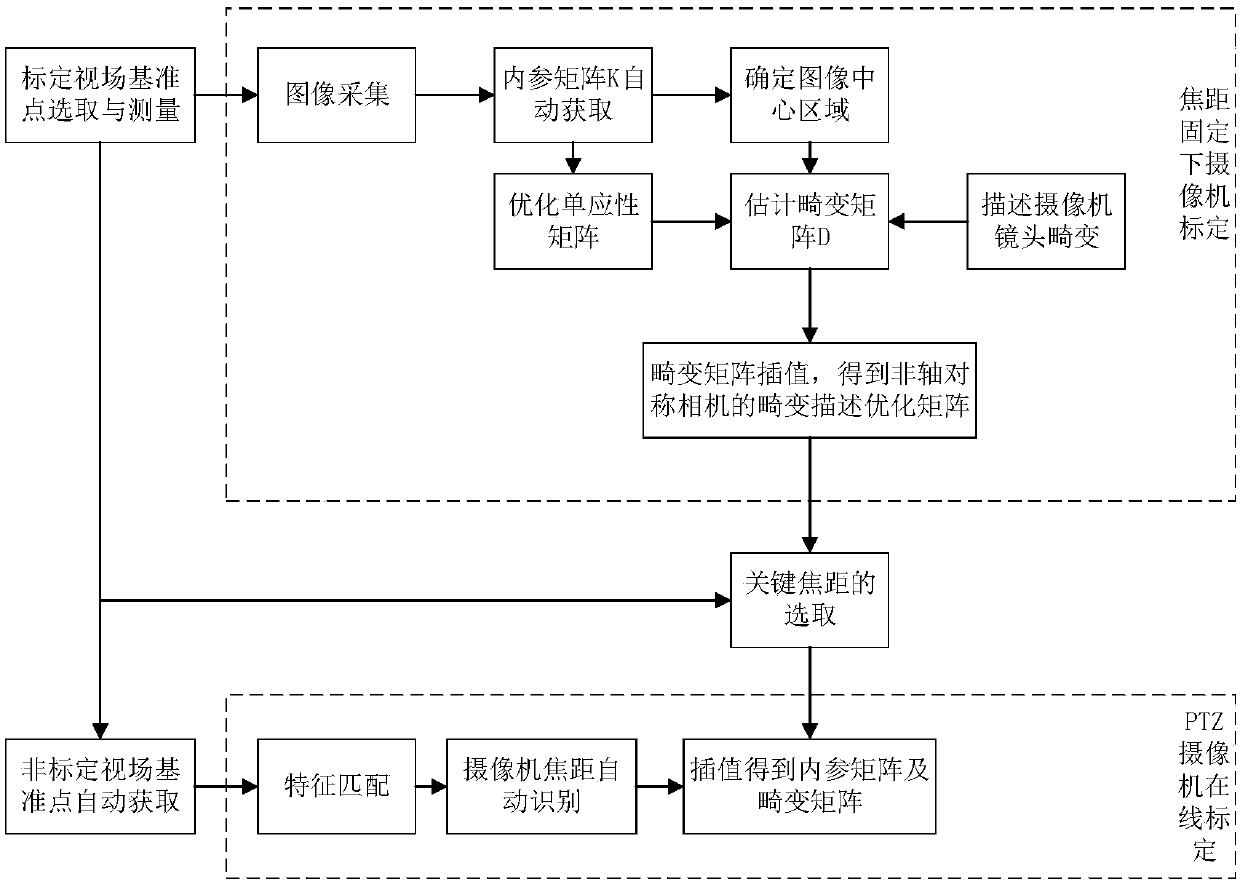
[0024] A PTZ camera on-site calibration and focusing method, the process is as follows figure 1 shown, including the following steps:

[0025] Step 1: Select and measure the reference point of the calibration field of view;

[0026] The present invention uses the known reference point information for calibr...


PUM


Abstract

The invention discloses a PTZ camera field calibration and focus fixing method and belongs to the technical fields of computer vision and camera calculation. The method comprises the steps of first, calibration field datum point selection and measurement; second, camera calibration under a fixed focal length; third, selection of a key focal length; fourth, automatic acquisition of non-calibrationfield datum points; and fifth, PTZ camera online calibration. Through the method, according to a non-strict axial symmetry lens, a method capable of effectively realizing distortion correction of thenon-strict axial symmetry lens is designed; since the datum points covering a whole camera field are obtained, the calibration workload is reduced, distortion of different regions of the lens can be described, and effective estimation of distortion under all focal lengths is realized; and by use of the invariance of an included angle between the datum points in a camera field, the focal length isquickly determined through a least square method, and distortion correction data of each point is obtained through interpolation.

Description

technical field [0001] The invention belongs to the technical field of computer vision and camera calibration, and in particular relates to a method for on-site calibration and focusing of a PTZ camera. Background technique [0002] PTZ (Pan-Tilt-Zoom, PTZ) camera, also known as zoom pan-tilt camera, can automatically adjust and control the focus distance, attitude, aperture, etc. It has the characteristics of flexibility, large field of view, and strong adaptability to lighting conditions. Therefore, it has been widely used in various fields such as video surveillance, electronic security, and robot navigation. The PTZ camera is used in the field of visual measurement, which solves the problems of small measurement viewing angle range and fixed viewing angle and direction, and reduces the requirements for the number of cameras while increasing the flexibility of the visual measurement system. [0003] In order to improve the accuracy of visual measurement, it is often nece...

Claims


Application Information

Patent Timeline
Patent Type & Authority Applications(China)
IPC IPC(8): G06T7/80G06T5/00
CPCG06T7/80G06T5/80
Inventor 张海陈洁灵
Owner BEIHANG UNIV
Learn More