
Lens distortion correction method and device

A lens distortion and correction method technology, which is applied in image data processing, television, color television, etc., can solve the problems of limited performance, low efficiency, and high cost of correction methods, and achieve the effect of lens distortion correction and low cost

Active Publication Date: 2014-11-19
HUAWEI TECH CO LTD
View PDF4 Cites 0 Cited by
  • Summary
  • Abstract
  • Description
  • Claims
  • Application Information

AI Technical Summary

Problems solved by technology

The DDR write addresses of the pixels of the corrected image are continuous. In order to ensure that the DDR write addresses of the corrected pixels are continuous, the DDR read addresses of the pixels of the original image before correction cannot meet the continuity, resulting in the corresponding pixel The point DDR cannot perform continuous reading according to the read address, but can only skip the non-sequential addresses, and the DDR read operation requires a refresh cycle, which cannot be read continuously, resulting in low DDR read efficiency, which is unacceptable in product implementation.
[0006] Although the DDR read address of the corresponding pixel is discontinuous, other useless pixel data including the corresponding pixel can be read continuously to ensure the read address is continuous, and the block size read out at one time is equal to "continuous length * continuous number ", the continuous length refers to the continuous reading in one refresh cycle, the sum of the readable pixels, when a distortion is encountered, the continuous reading stops, the continuous length can be the horizontal length in the horizontal direction, and the continuous number refers to the system allows The number of consecutive reading restarts in the DDR one-time read block. The continuous length can be the vertical column length in the vertical direction. The continuous length and the continuous number here are determined by the degree of radial distortion, but "continuous length * continuous The "number" is also limited by the performance of the product. When the radial distortion is large, the "continuous length * continuous number" determined by it will exceed the performance limit of the product, so that the read address cannot be guaranteed to be continuous.
[0007] The cost of the above correction methods is too high and the efficiency is low, therefore, a low-cost and high correction efficiency lens distortion correction method and device are needed

Method used


Image

  • Lens distortion correction method and device
  • Lens distortion correction method and device
  • Lens distortion correction method and device

Examples


Embodiment Construction

[0062] The following will clearly and completely describe the technical solutions in the embodiments of the present invention with reference to the accompanying drawings in the embodiments of the present invention. Obviously, the described embodiments are only some, not all, embodiments of the present invention. Based on the embodiments of the present invention, all other embodiments obtained by persons of ordinary skill in the art without creative efforts fall within the protection scope of the present invention.

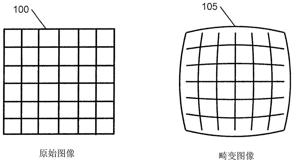
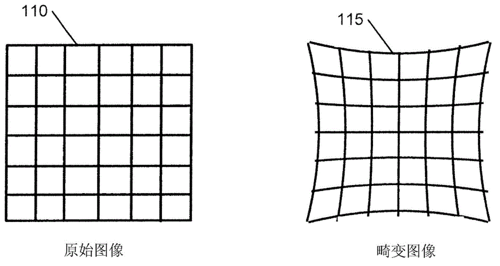
[0063] Lens distortion is an optical aberration that occurs when the imaged object is not positioned on the optical axis of the lens. The result is a discrepancy between the coordinates of the digital image and the coordinates of the object. Among the various types of lens distortion, the radial distortion that deviates from the optical center of the digital image along the radial line is one of the most common and serious types

[0064] A digital image with radia...


PUM


Abstract

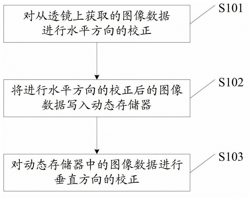
A lens distortion correction method and device; in some feasible embodiments of the present invention: horizontally correcting the image data acquired from a lens; writing the horizontally corrected image data into a dynamic memory; and vertically correcting the image data written in the dynamic memory. The two steps for correcting horizontal and vertical lens distortion realize lens distortion correction at a low cost. Also disclosed is a corresponding lens distortion correction device.

Description

technical field [0001] The present invention relates to a lens distortion error generated when an image sensor captures an image, and more particularly relates to a method and device for correcting lens distortion of a digital image. Background technique [0002] Lens distortion is one of the most important factors affecting the quality of digital images produced by image sensors, and it is necessary to correct the distorted images. [0003] The most commonly used method for correcting lens distortion in digital images is to use the following two methods to correct digital images in place at one time: [0004] One approach is to use an in-line line buffer to achieve a one-shot correction of lens distortion. The method corrects the lens distortion in the horizontal and vertical directions while acquiring image data from the lens. One-time correction requires a large number of line buffers to store coordinate data of distorted lines. This line buffer is a small temporary sto...

Claims


Application Information

Patent Timeline
Patent Type & Authority Patents(China)
IPC IPC(8): H04N5/357H04N9/04
CPCH04N5/3572G06T5/006G06T3/0018H04N25/61G06T5/002
Inventor 李水平邓安刚许聪
Owner HUAWEI TECH CO LTD
Learn More