
Flowmeter based on engineering mechanics

A technology of engineering mechanics and flowmeter, which is applied in the field of engineering mechanics, can solve problems such as the great influence of refracted wave intensity attenuation, ultrasonic signal beam offset, and unfavorable high-precision measurement, so as to avoid refraction attenuation and beam offset, and improve measurement Accuracy, the effect of improving accuracy

Inactive Publication Date: 2018-10-12
SICHUAN UNIVERSITY OF SCIENCE AND ENGINEERING
View PDF6 Cites 0 Cited by
  • Summary
  • Abstract
  • Description
  • Claims
  • Application Information

AI Technical Summary

Problems solved by technology

[0006] (1) If the diameter d of the small pipe diameter is less than 10mm, because the ultrasonic propagation path l is Therefore, the ultrasonic propagation time is very small, below the nanosecond level. If the measurement accuracy is 1%, the time resolution of the flowmeter system must be hundreds of picoseconds, so the design requirements for the ultrasonic flowmeter measurement system are very high. , is not easy to achieve;
[0007] (2) When the ultrasonic waves propagate at the interface between the liquid and the pipe wall, the included angle It has a great influence on the attenuation of the refracted wave intensity. When the liquid flow rate is too high, the ultrasonic signal has a beam shift phenomenon, and the ultrasonic signal received by the corresponding receiving transducer is significantly attenuated, which is not conducive to high-precision measurement

Method used


Image

  • Flowmeter based on engineering mechanics
  • Flowmeter based on engineering mechanics
  • Flowmeter based on engineering mechanics

Examples


Embodiment Construction

[0032] The following will clearly and completely describe the technical solutions in the embodiments of the present invention with reference to the accompanying drawings in the embodiments of the present invention. Obviously, the described embodiments are only some, not all, embodiments of the present invention. Based on the embodiments of the present invention, all other embodiments obtained by persons of ordinary skill in the art without making creative efforts belong to the protection scope of the present invention.

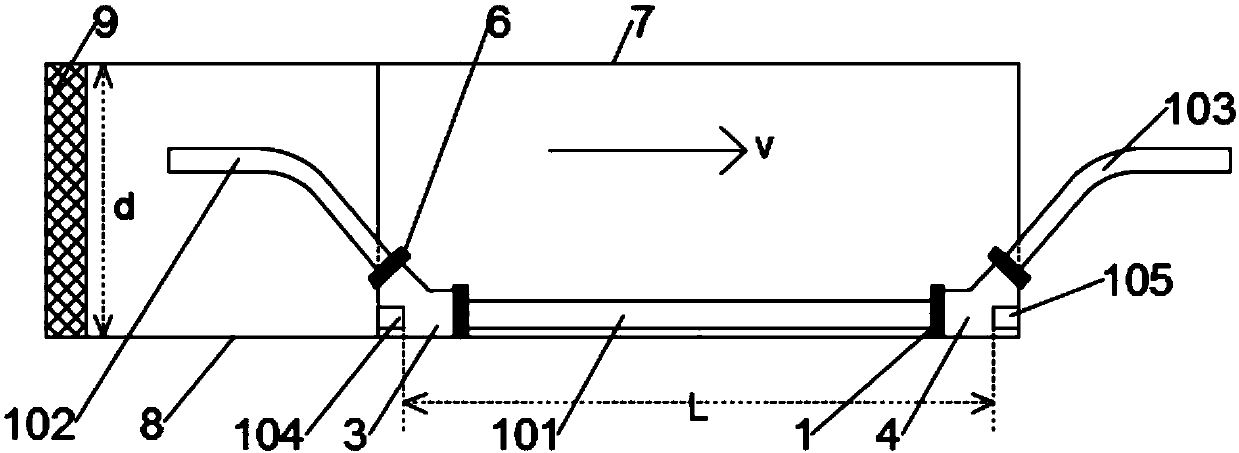
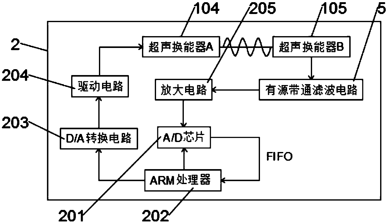
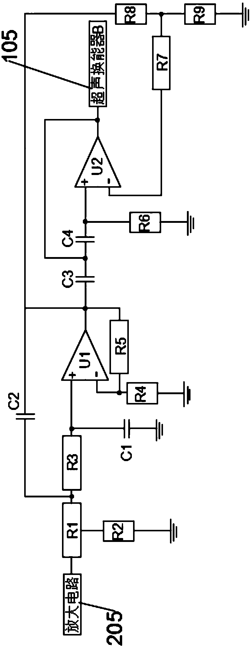
[0033] like Figure 1 to Figure 4 As shown, the present invention provides a flow meter based on engineering mechanics, including a flow detection device 1 and a data acquisition system 2, one end of the data acquisition system 2 is connected to the flow detection device 1, and the flow detection device 1 includes a central straight Pipe 101, left curved pipe 102, right curved pipe 103, ultrasonic transducer A104 and ultrasonic transducer B105, the left curved...


PUM


Abstract

The invention discloses a flowmeter based on engineering mechanics. The flowmeter comprises a flow detecting device and a data collecting system, one end of the data collecting system is connected with the flow detecting device, the flow detecting device comprises a middle straight pipe, a left curved pipe, a right curved pipe, an ultrasonic transducer A and an ultrasonic transducer B, he left curved pipe and the right curved pipe are respectively disposed at the left and right ends of the middle straight pipe, a connection head A is arranged at the joint between the left curved pipe and the left end of the middle straight pipe, a connection head B is arranged between the right curved pipe and the right end of the middle straight pipe, the ultrasonic transducer A and the ultrasonic transducer B are respectively disposed outside the connection head A and the connection head B, and the ultrasonic transducer A and the ultrasonic transducer B are arranged on the same horizontal line; the flowmeter solves the problem of refractive attenuation and beam offset of ultrasonic waves during propagation, achieves a high-precision and high-efficiency fluid measurement function, and ensures accurate and reliable measurement results.

Description

technical field [0001] The invention relates to the technical field of engineering mechanics, in particular to a flowmeter based on engineering mechanics. Background technique [0002] Engineering mechanics involves many branches of mechanics disciplines and a wide range of engineering technology fields. It is a technically basic subject with strong theory and close relationship with engineering technology. The theorems, laws and conclusions of engineering mechanics are widely used in engineering in all walks of life. In technology, it is an important basis for solving practical engineering problems, and its most basic parts include statics and mechanics of materials. [0003] When solving practical engineering problems based on engineering mechanics, flowmeters are often used. According to the most popular and extensive classification methods, flowmeters can be divided into: differential pressure flowmeter, vortex flowmeter, turbine flowmeter, and float flowmeter. Meter, d...

Claims


Application Information

Patent Timeline
Patent Type & Authority Applications(China)
IPC IPC(8): G01F1/66
Inventor 梁超黄华司马卫平廖熠唐恒军
Owner SICHUAN UNIVERSITY OF SCIENCE AND ENGINEERING
Learn More