Hydraulic slurry pump

A mud pump and hydraulic technology, applied in the field of hydraulic mud pump, can solve the problems of inconvenient replacement, reduced production efficiency, instability, etc., and achieve the effects of convenient processing, simple structure and compact structure

Active Publication Date: 2018-10-12
JIANGSU YANBANG PUMP MFG CO LTD
View PDF6 Cites 4 Cited by
  • Summary
  • Abstract
  • Description
  • Claims
  • Application Information

AI Technical Summary

Problems solved by technology

Especially in the field of mud pump application technology, the traditional mud pump uses a crank connecting rod mechanism to realize the reciprocating movement of the piston in the cylinder to pump the mud out. In addition, in the current hydraulic mud pump, the reversing valve that realizes the reciprocating movement of the piston mostly uses an electromagnetic reversing valve and a displacement sensor to control the reversing. The sensor is controlled by a proximity switch, and the reversing is unstable. Unreliable, complex structure, and inconvenient replacement; the control circuit part of the reversing device is controlled by a circuit board, because the circuit board is a non-standard part, and it is difficult to manufacture and process, and it is very difficult to repair after damage. It is inconvenient to find the reason, which greatly reduces the production efficiency; if the existing reversing device is continuously powered on for a long time, it is easy to damage small devices, which can meet the requirements of long-term power supply, and also affects the production efficiency to a certain extent

Method used


Image

  • Hydraulic slurry pump
  • Hydraulic slurry pump
  • Hydraulic slurry pump

Examples


Embodiment Construction

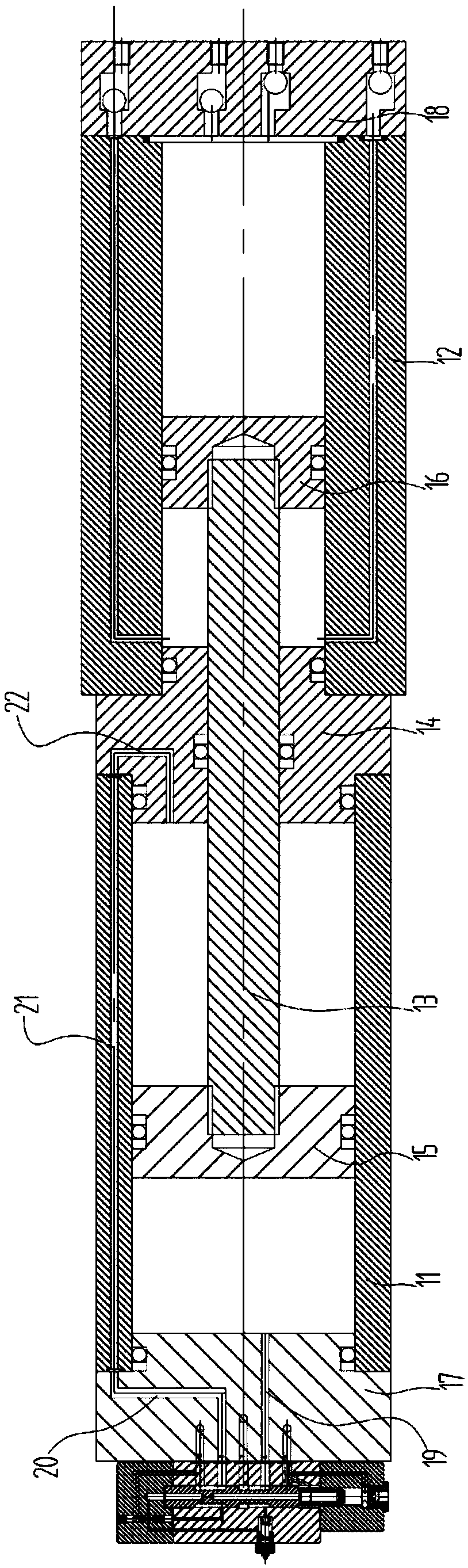
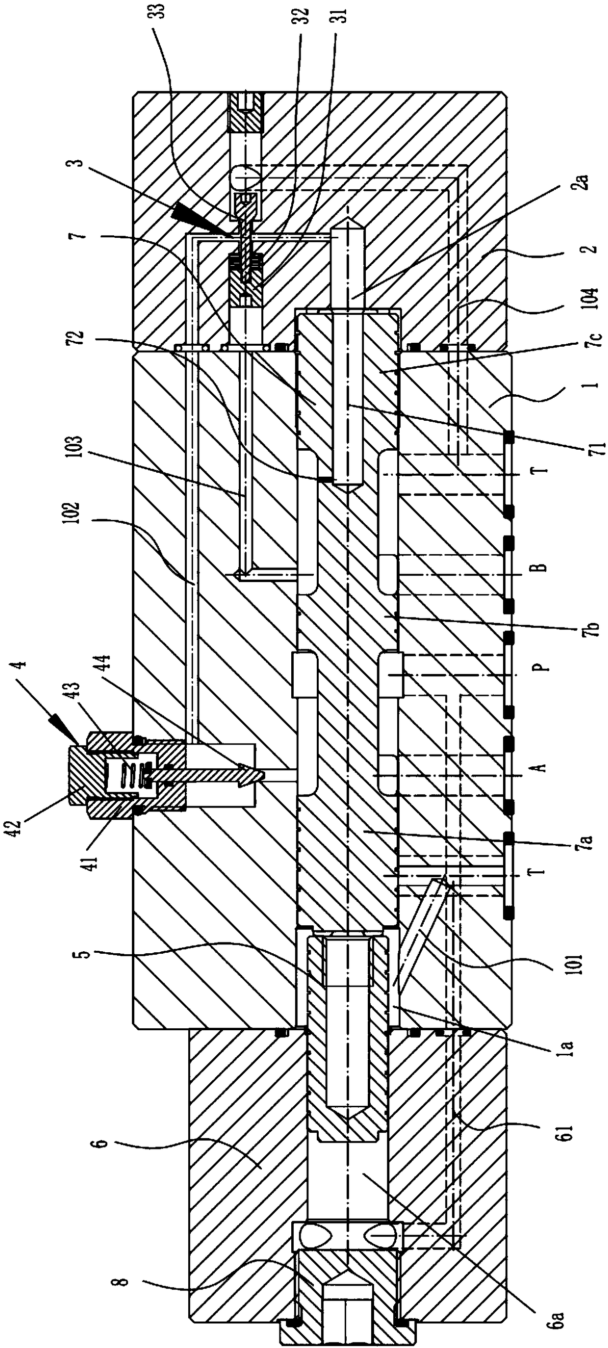
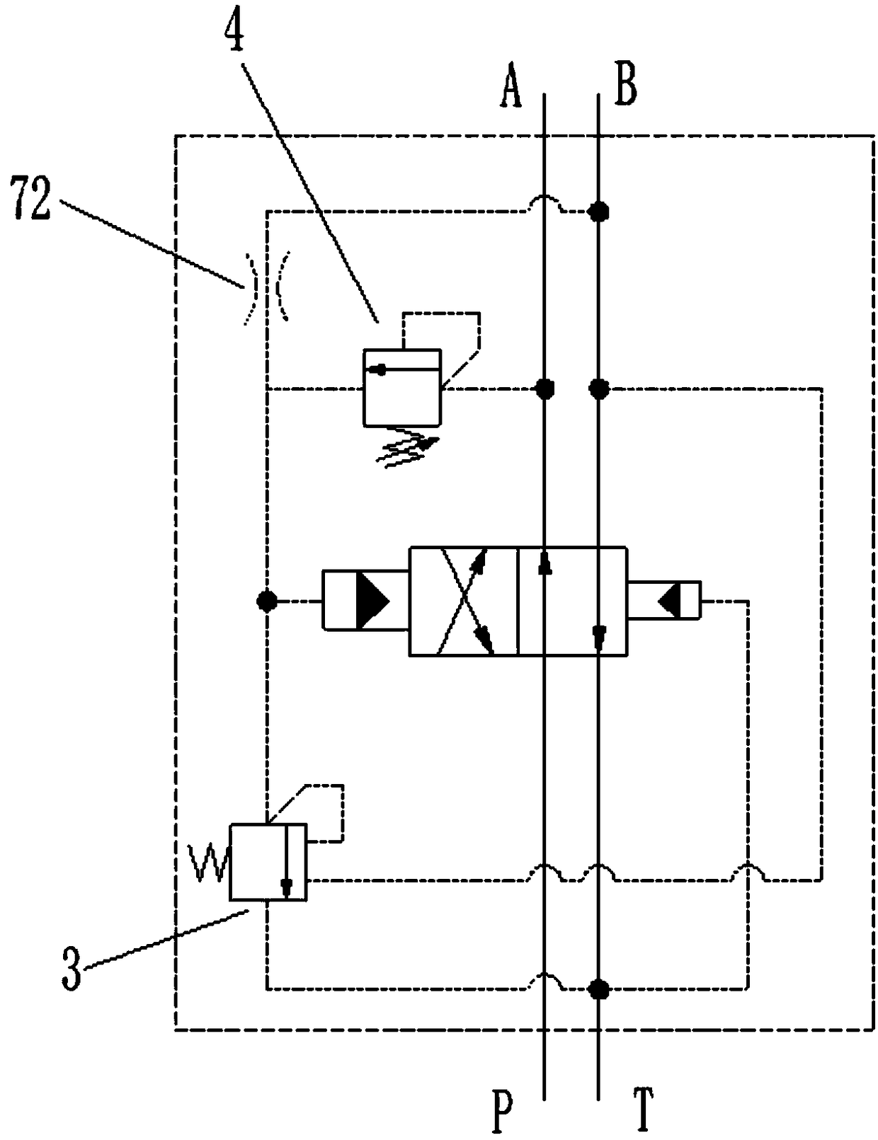
[0019] see Figure 1-3 , the present invention provides a hydraulic mud pump, comprising a hydraulic cylinder block 11, a mud pump body 12, a piston rod 13, and an body 11 and the connecting block 14 of the mud pump body 12; the piston rod 13 is slidably connected in the connecting block 14, and its left end is located in the hydraulic cylinder block 11, and the right end is located in the mud pump body 12 Inside; the hydraulic cylinder 11 is slidably connected with a hydraulic piston 15 connected to the left end of the piston rod 13, and the mud pump body 12 is slidably connected with a mud piston 16 connected with the right end of the piston rod 13; The left end of the hydraulic cylinder body 11 is equipped with a hydraulic end cover 17, and the hydraulic end cover 17 is provided with a reversing valve for controlling the reciprocating movement of the hydraulic piston 15; the right end of the mud pump body 12 is equipped with a mud end cover 18 , The mud end cover 18 is pro...


PUM


Abstract

The invention discloses a hydraulic slurry pump. The hydraulic slurry pump comprises a hydraulic cylinder body, a slurry pump body, a piston rod, and a connecting block which is arranged between the hydraulic cylinder body and the slurry pump body and used for connecting the hydraulic cylinder body and the slurry pump body. The piston rod is connected in the connecting block in a sliding mode, theleft end of the piston rod is located in the hydraulic cylinder body, and the right end of the piston rod is located in the slurry pump body. A hydraulic piston connected with the left end of the piston rod is connected in the hydraulic cylinder body in a sliding mode, and a slurry piston connected with the right end of the piston rod is connected in the slurry pump body in a sliding mode. A hydraulic end cover is installed at the left end of the hydraulic cylinder body and provided with a reversing valve for controlling the reciprocating motion of the hydraulic piston. A slurry end cover isinstalled at the right end of the slurry pump body and provided with a one-way valve assembly for controlling slurry to get into and out of the slurry pump body. The slurry pump is not only simple instructure but also free of electric control.

Description

technical field [0001] The invention relates to the technical field of mud pumps, in particular to a hydraulic mud pump. Background technique [0002] With the large-scale application of large-scale mechanical equipment, hydraulic drive has been widely used as a very important driving method, and the hydraulic system and its related technologies are becoming more and more mature. Especially in the field of mud pump application technology, the traditional mud pump uses a crank-connecting rod mechanism to realize the reciprocating movement of the piston in the cylinder to pump the mud out. In addition, in the current hydraulic mud pump, the reversing valve that realizes the reciprocating movement of the piston mostly uses an electromagnetic reversing valve and a displacement sensor to control the reversing, and the sensor is controlled by a proximity switch, and the reversing is unstable. Unreliable, complex structure, and inconvenient replacement; the control circuit part of...

Claims


Application Information

Patent Timeline
Patent Type & Authority Applications(China)
IPC IPC(8): F04B15/02F04B9/113F04B49/00
CPCF04B9/113F04B15/02F04B49/002
Inventor 邵玉刚
Owner JIANGSU YANBANG PUMP MFG CO LTD
Why Eureka
Try Eureka