Railway construction machinery guard rail lifting device

A technology for construction machinery and guard rails, which is applied in the field of recovery devices for railway construction machinery guard rails. It can solve problems such as rebounding of recovery pressure, reduction of connection transmission, and lack of smoothness of runner rotation, etc., to reduce the probability of track loss and simplify the operation. The effect of mechanical structure

Inactive Publication Date: 2018-10-12
南安紫鲸铃工业设计有限公司
View PDF6 Cites 0 Cited by
  • Summary
  • Abstract
  • Description
  • Claims
  • Application Information

AI Technical Summary

Problems solved by technology

[0003] In view of the deficiencies in the prior art, the purpose of the present invention is to provide a railway construction machinery guard rail lifting device to solve the lack of telescopic rotation and speed regulation of the jack or piston cylinder by the guard rail lifting device, which may easily lead to Falling off the track in advance, insufficient control of the pressure and speed during the connection process, resulting in a lack of fluency in the overall runner rotation, and excessive rotation and transmission causing the recovery pressure to bounce off the track, failing to achieve the effect of speed regulation and reducing the connection transmission

Method used


Image

  • Railway construction machinery guard rail lifting device
  • Railway construction machinery guard rail lifting device
  • Railway construction machinery guard rail lifting device

Examples


Embodiment Construction

[0024] In order to make the technical means, creative features, goals and effects achieved by the present invention easy to understand, the present invention will be further described below in conjunction with specific embodiments.

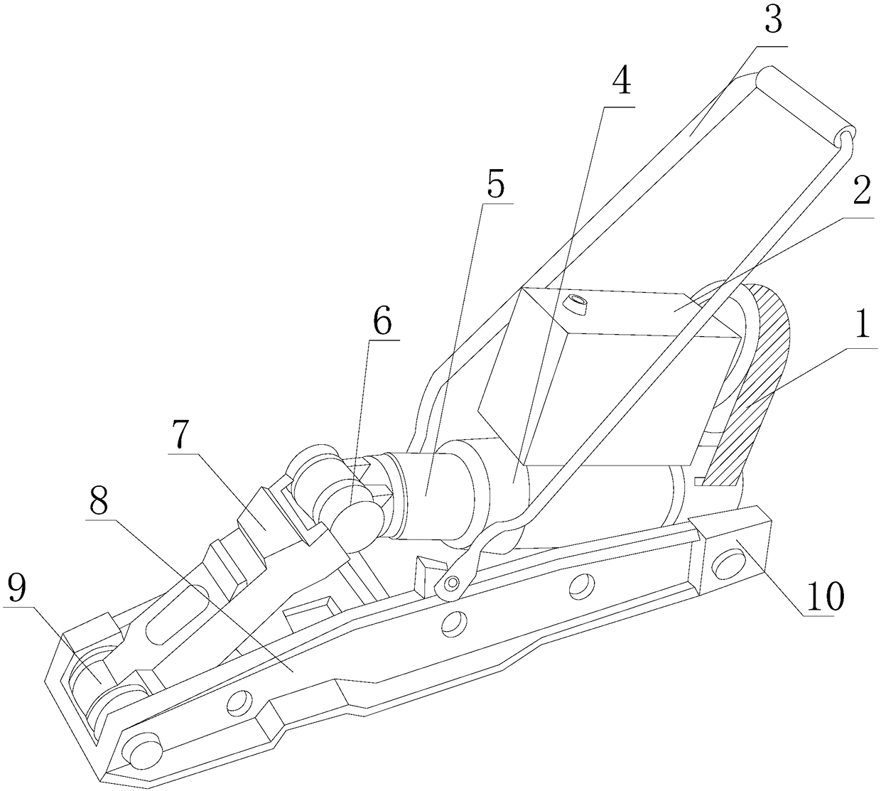
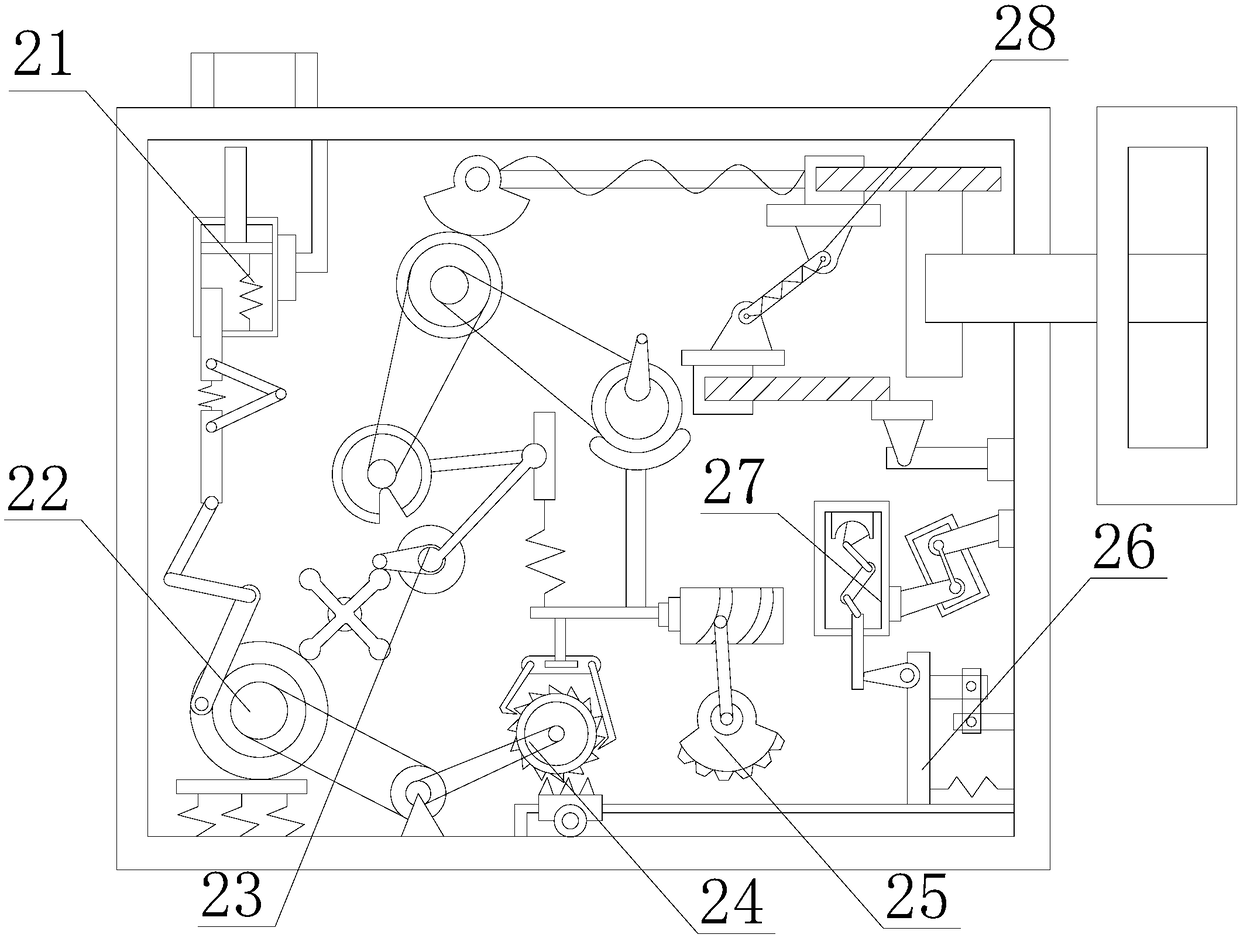
[0025] see Figure 1-Figure 5 , the present invention provides a railway construction machinery guard rail lifting device, its structure includes: shaft wheel conveyor belt 1, wheel speed control box 2, inclined frame handle rod 3, plunger hydraulic cylinder 4, alloy plunger barrel 5, joint roller Wheel 6, guard rail splint 7, lifting groove base 8, hinge roller column 9, rubber fastening block 10, the shaft wheel conveyor belt 1 is inserted on the right side of the runner speed control box 2, and the runner The bottom surface of the speed control box 2 is closely attached to the top surface of the plunger hydraulic cylinder 4. The alloy plunger barrel 5 is inserted on the left side of the plunger hydraulic cylinder 4 and the axes are collinear. T...


PUM


Abstract

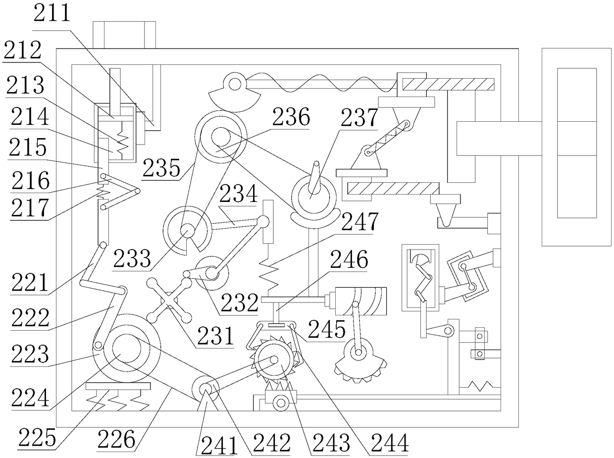
The invention discloses a railway construction machinery guard rail lifting device. The railway construction machinery guard rail lifting device structurally comprises an arbor wheel conveyor belt, arotating wheel speed control box, an inclined frame handle rod, a plunger hydraulic cylinder, an alloy plunger barrel, a joint round screw die, a guard rail clamping plate, a lifting groove base, a hinge roller column and rubber fastening blocks, and the arbor wheel conveyor belt is embedded in the right side of the rotating wheel speed control box in an inserted mode. The turning wheel speed control box is provided with a piston cylinder pressure jacking device, a turntable transmission mechanism, an intermittent transmission device, a ratchet rotation mechanism, a fan disk pendulum device, asliding block collision mechanism, an internal combustion cylinder friction device and a rubber tube clamping mechanism, the adjustment effect is achieved by controlling the rotational speed of a rotating wheel while realizing lifting of the guard rail lifting device by using the hydraulic cylinder, the output rate of a rotating wheel conveyor belt can be changed to be matched with the self-weight of different guard rails to carry out the operation of pressure-resistant lifting, an integrated simple mechanical structure is achieved, the internal connection transmission directly affects the lifting process, and the rail drop-off probability is greatly reduced.

Description

technical field [0001] The invention relates to a rail guard lifting device for a railway construction machine, which belongs to the field of railway construction and rail guard lifting equipment. Background technique [0002] Various civil engineering facilities on the railway also refer to the technologies used in various stages of railway construction such as survey design, construction, maintenance, and reconstruction. Railway engineering initially includes civil engineering related to railways such as tracks, roadbeds, bridges, tunnels, and stations. , machinery and signal engineering, the current technology of the guard rail recovery device lacks the telescopic rotation speed regulation of the jack or the piston cylinder, which may easily lead to the early fall of the guard rail during the recovery process, and insufficient control of the pressure and speed during the connection process , so that the smoothness of the overall runner rotation is lacking, and the over-ro...

Claims


Application Information

Patent Timeline
Patent Type & Authority Applications(China)
IPC IPC(8): E01B29/16
Inventor 黄连福黄金良黄佳彬
Owner 南安紫鲸铃工业设计有限公司
Why Eureka
Try Eureka