Clamping mechanism for circular electroplating part

A technology of clamping mechanism and electroplating parts, applied in the direction of electrolysis components, electrolysis process, etc., can solve the problems of time-consuming, laborious, troublesome operation, etc., and achieve the effects of easy installation and fixation, convenient electroplating, and simple operation.

Pending Publication Date: 2018-10-12
浙江贝耐特工具有限公司
View PDF12 Cites 5 Cited by
  • Summary
  • Abstract
  • Description
  • Claims
  • Application Information

AI Technical Summary

Problems solved by technology

[0004] For this reason, the technical problem to be solved by the present invention is that the clamps used for circular electroplating parts in the prior art need to undergo secondary electroplating to achieve full electroplating, and the operation is cumbersome, time-consuming and laborious. Clamping mechanism

Method used


Image

  • Clamping mechanism for circular electroplating part
  • Clamping mechanism for circular electroplating part
  • Clamping mechanism for circular electroplating part

Examples


Embodiment Construction

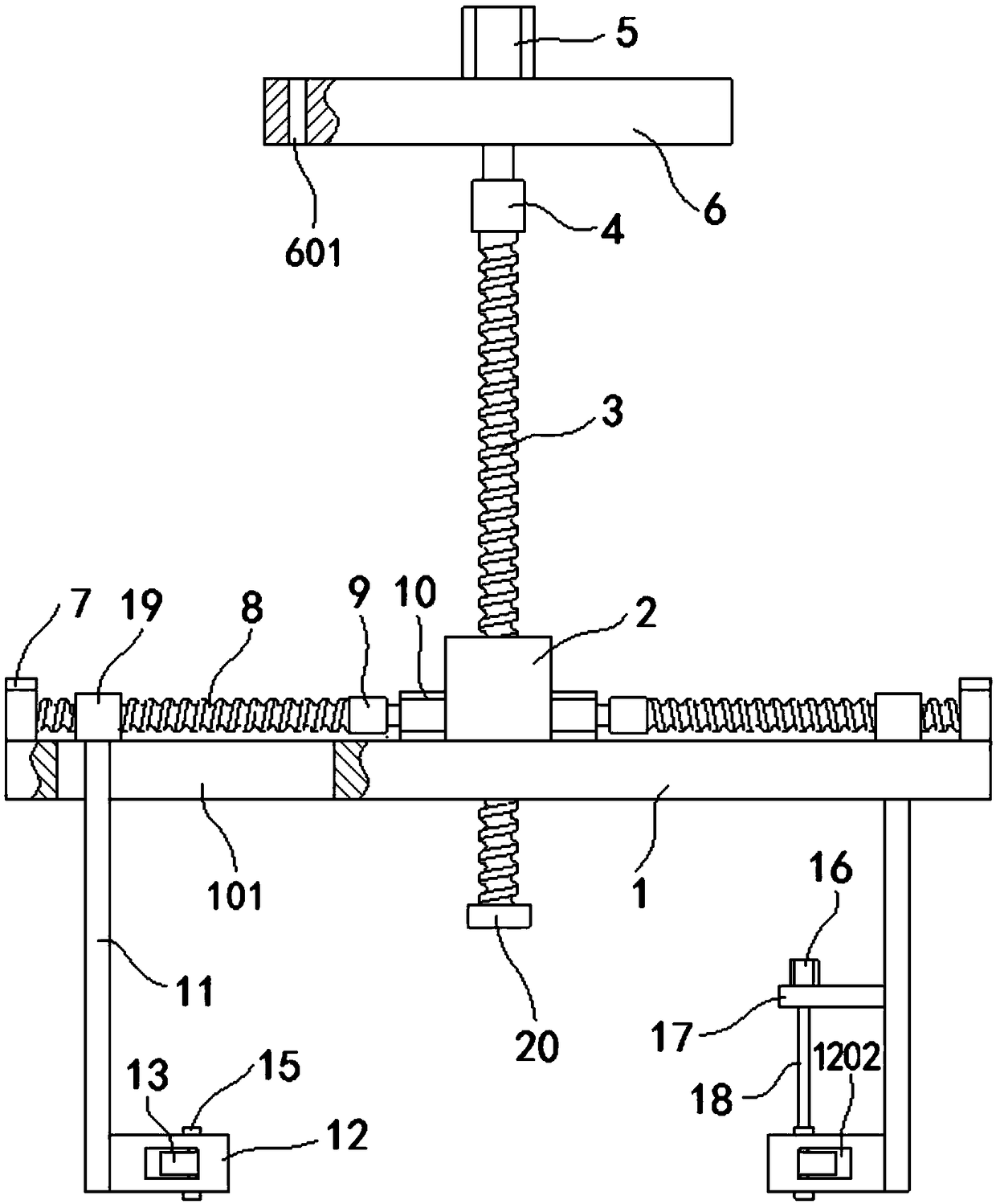
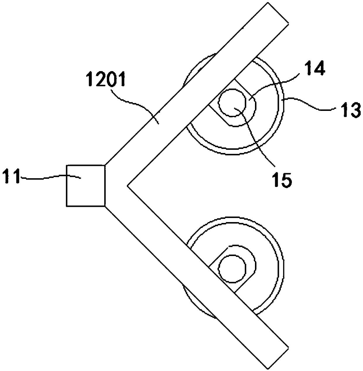
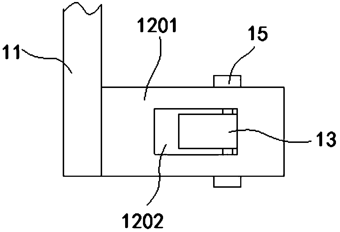
[0020] like figure 1 , figure 2 , image 3 Shown, a kind of clamping mechanism that is used for circular plating piece of the present invention comprises:

[0021] A horizontal support plate 1, the middle part of the upper surface of the support plate 1 is formed with a fixed block 2, the fixed block 2 is screwed on the first lead screw 3, and the lower end of the first lead screw 3 passes through the support Plate 1, the upper end of the first lead screw 3 is connected to the first end of the first coupling 4, the second end of the first coupling 4 is connected to the output shaft of the first stepper motor 5, the The first stepping motor 5 is arranged on the upper surface of the mounting plate 6 . Both ends of the upper surface of the support plate 1 are respectively formed with bearing seats 7, and the two sides of the upper end of the support plate 1 are respectively provided with second screw screws 8, and the first ends of the second screw screws 8 are hinged on the ...


PUM


Abstract

The invention discloses a clamping mechanism for a circular electroplating part. The clamping mechanism comprises a supporting plate, a fixing block, a first lead screw, a first coupling, a first stepping motor, a mounting plate, a bearing block, a second lead screw, a second coupling, a second stepping motor, a connecting rod, V-shaped clamping plates, rolling wheels and the like. According to the clamping mechanism for the circular electroplating part, the V-shaped clamping plates are arranged on the two sides of the lower end of the supporting plate correspondingly, clamping of the circularelectroplating part is realized through the rolling wheels on the V-shaped clamping plates, and the rotation of the electroplating part can be realized through the rotation of the rolling wheels so that the whole circular electroplating part can be conveniently electroplated; the first stepping motor is arranged at the upper end of the supporting plate, and the supporting plate and the electroplating part clamped by the rolling wheels can be driven to move up and down so that the electroplating part can be conveniently put into an electroplating tank for electroplating; and a rotating motor is arranged above one rolling wheel, and is used for driving a first stopping block to rotate so that the roling wheels can be rotated to drive the electroplating part to rotate, and electroplating ofthe clamping part can be realized without the action of external force.

Description

Technical field: [0001] The invention belongs to the technical field of auto parts equipment, and in particular relates to a clamping mechanism for circular electroplating parts. Background technique: [0002] Electroplating is the process of plating a thin layer of other metals or alloys on the surface of certain metals using the principle of electrolysis. It is a process of using electrolysis to attach a layer of metal film to the surface of metal or other material parts to prevent metal oxidation ( Such as rust), improve wear resistance, electrical conductivity, reflective properties, corrosion resistance (copper sulfate, etc.) and enhance the appearance. [0003] Many parts of automobiles need to be electroplated during processing, especially some cylindrical electroplated parts need to be clamped in the electroplating tank by a fixture for surface treatment, but when the existing fixture clamps the electroplated part, its clamping part and electroplating If the parts a...

Claims


Application Information

Patent Timeline
Patent Type & Authority Applications(China)
IPC IPC(8): C25D17/06C25D7/00
CPCC25D7/00C25D17/06
Inventor 徐国飞罗中鑫屠晓清葛洪斌陈海娣
Owner 浙江贝耐特工具有限公司
Why Eureka
Try Eureka