
Novel charging device for new energy vehicle

A new energy vehicle and charging device technology, which is applied to electric vehicle charging technology, circuit devices, battery circuit devices, etc., can solve the problems of affecting normal use, prone to damage, and short service life, so as to facilitate charging and improve cleanliness. , the effect of improving usability

Inactive Publication Date: 2018-10-12
TAIZHOU LIWEI ENVIRONMENTAL TECH CO LTD
View PDF8 Cites 6 Cited by
  • Summary
  • Abstract
  • Description
  • Claims
  • Application Information

AI Technical Summary

Problems solved by technology

[0002] New energy vehicles refer to vehicles that use unconventional vehicle fuels as the power source, integrate advanced technologies in vehicle power control and drive, and form vehicles with advanced technical principles, new technologies, and new structures. and excellent performance are loved by more and more consumers. In order to ensure the normal driving of new energy vehicles, charging devices are usually installed in residential areas or public parking lots. Most of the existing charging devices are simple in structure and single in function. They all use mains power to provide electric energy. Not only is the work cost high, but it is also easily affected by emergencies such as power outages, and the practicability is low. In addition, most of the charging devices are fixed. , not only affects its normal use, but also prone to damage, short service life and poor safety

Method used


Image

  • Novel charging device for new energy vehicle
  • Novel charging device for new energy vehicle
  • Novel charging device for new energy vehicle

Examples


Embodiment Construction

[0023]The following will clearly and completely describe the technical solutions in the embodiments of the present invention with reference to the accompanying drawings in the embodiments of the present invention. Obviously, the described embodiments are only some, not all, embodiments of the present invention. Based on the embodiments of the present invention, all other embodiments obtained by persons of ordinary skill in the art without making creative efforts belong to the protection scope of the present invention.

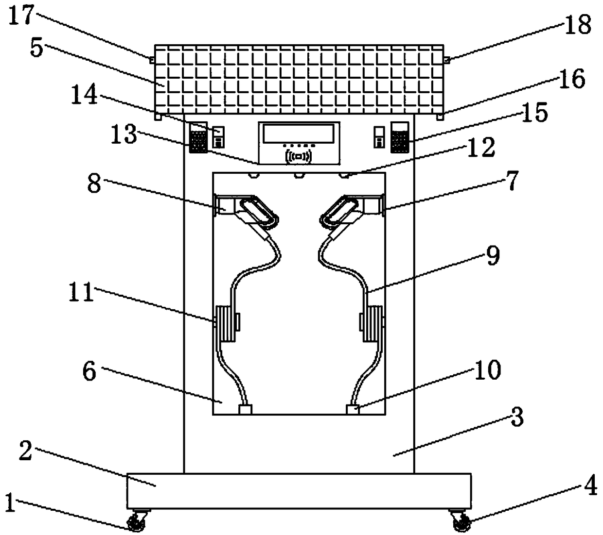
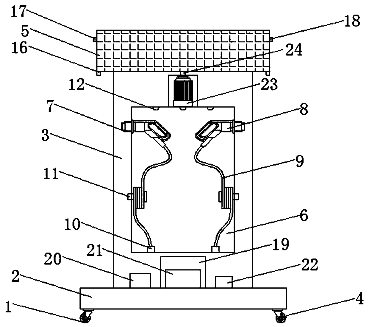
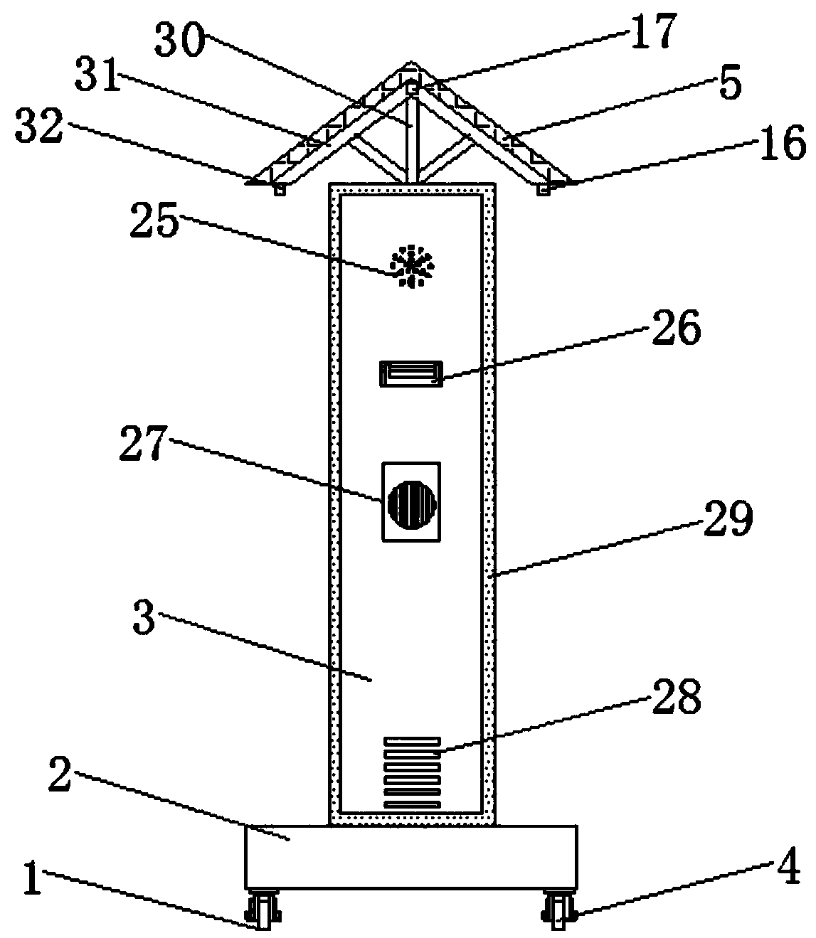
[0024] see Figure 1-5 , the present invention provides a technical solution: a new type of new energy vehicle charging device, including a device body 1, a base 2, a charging pile 3, casters 4, a solar panel 5, a slot 6, a charging gun seat 7, a charging gun 8. Charging cable 9, charging cable interface 10, winding seat 11, LED lighting 12, operation panel 13, USB charging port 14, placement slot 15, first DZD-T4 light sensor 16, MH-YLC rain sensor 17, HL504H...


PUM


Abstract

The invention discloses a novel charging device for a new energy vehicle. The bottom of a device body is provided with a base. The top of a base is provided with a charging pile. A through groove is formed in the middle portion of the charging pile, and the top of the through groove is provided with an LED lighting lamp. Charging gun bases are mounted on the top ends of two sides of the through groove, and charging guns are disposed inside the charging gun bases. An operation panel is installed on the middle portion of the front end of the charging pile, USB charging ports are installed on both sides of the operation panel, and placing grooves are formed in one sides of the USB charging ports. An Y355 motor is installed on the middle portion of the top end in the charging pile. The top endof the Y355 motor is fixedly connected with a rotating shaft. The top end of the rotating shaft is fixedly connected with a supporting frame. The top of the supporting frame is provided with mountingplates, and solar panels are laid at the tops of the mounting plates. Casters are mounted at the bottom of the base. A protective net which can be used for holding smart products such as mobile phones and tablet computers is mounted on the outer side of the placing groove and is convenient for charging the smart products such as mobile phones and tablet computers, and the practicability of the device body is further improved.

Description

technical field [0001] The invention relates to the technical field of new energy vehicles, in particular to a new charging device for new energy vehicles. Background technique [0002] New energy vehicles refer to vehicles that use unconventional vehicle fuels as the power source, integrate advanced technologies in vehicle power control and drive, and form vehicles with advanced technical principles, new technologies, and new structures. and excellent performance are loved by more and more consumers. In order to ensure the normal driving of new energy vehicles, charging devices are usually installed in residential areas or public parking lots. Most of the existing charging devices are simple in structure and single in function. They all use mains power to provide electric energy. Not only is the work cost high, but it is also easily affected by emergencies such as power outages, and the practicability is low. In addition, most of the charging devices are fixed. , not only ...

Claims


Application Information

Patent Timeline
Patent Type & Authority Applications(China)
IPC IPC(8): B60L11/18H02J7/35H02S20/30H05K7/20A01M1/22
CPCA01M1/226B60L53/31H02J7/35H02S20/30H05K7/20Y02E10/50Y02T10/70Y02T10/7072Y02T90/12
Inventor 许希杰袁鹏飞
Owner TAIZHOU LIWEI ENVIRONMENTAL TECH CO LTD
Learn More