
Engine exhaust aftertreatment mixing device and manufacturing method thereof

A technology for exhaust post-treatment and mixing devices, which is applied in the direction of exhaust devices, engine components, machines/engines, etc. It can solve problems such as mixer failure, falling off, and metal strip breakage, so as to reduce processing procedures, improve strength, and avoid effect of influence

Active Publication Date: 2021-10-22
TENNECO SUZHOU EMISSION SYST
View PDF0 Cites 0 Cited by
  • Summary
  • Abstract
  • Description
  • Claims
  • Application Information

AI Technical Summary

Problems solved by technology

At the same time, the contact point between each metal strip and the mixing tube is small, so it is difficult to ensure the effectiveness of welding for a long time with such a small welding point, so the metal strip is easy to break and fall off, resulting in the failure of the mixer

Method used


Image

  • Engine exhaust aftertreatment mixing device and manufacturing method thereof
  • Engine exhaust aftertreatment mixing device and manufacturing method thereof
  • Engine exhaust aftertreatment mixing device and manufacturing method thereof

Examples


Embodiment Construction

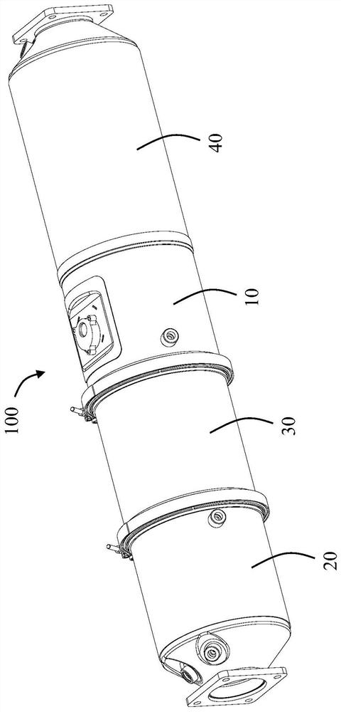
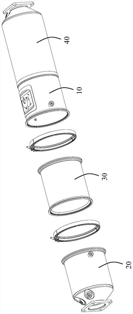
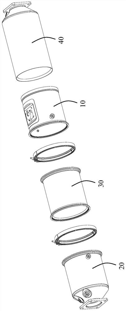
[0034] Please refer to Figure 1 to Figure 10 As shown, the present invention discloses an engine exhaust aftertreatment device 100, which is used in aftertreatment systems such as SCR to treat engine exhaust. The engine exhaust aftertreatment device 100 includes an engine exhaust aftertreatment mixing device 10, a diesel oxidation catalyst (DOC) 20 and a diesel particulate filter located upstream of the engine exhaust aftertreatment mixing device 10 and serially connected in series (DPF) 30 , and a selective catalytic reductant (SCR) 40 downstream of the engine exhaust aftertreatment mixing device 10 .

[0035] The engine exhaust aftertreatment mixing device 10 includes a housing 1, a mixing element 2 installed in the housing 1, and a fine fiber element 3 for further increasing the evaporation and pyrolysis of urea droplets.

[0036] In the illustrated embodiment of the present invention, the housing 1 is cylindrical, and it is provided with a mounting plate 11 recessed into...


PUM


Abstract

An engine exhaust gas aftertreatment mixing device, which includes a pipe body and a thin fiber element located in the pipe body for mixing exhaust gas with urea droplets, the pipe body has an inner wall and is surrounded by the inner wall The inner cavity is formed, wherein the fine fiber element is used for the exhaust gas and the urea droplet to pass through, so as to further increase the breakage and evaporation of the urea droplet. The fine fiber elements are brazed directly to the inner wall. Such setting, on the one hand, reduces the processing steps and reduces the processing cost; on the other hand, the strength of the thin fiber element is improved through integral brazing, and the risk of deformation and damage due to the impact of the engine exhaust pulse is reduced. The invention also relates to a method of manufacturing the above-mentioned engine exhaust aftertreatment mixing device.

Description

technical field [0001] The invention relates to an engine exhaust aftertreatment mixing device and a manufacturing method thereof, belonging to the technical field of engine exhaust aftertreatment. Background technique [0002] In the prior art, there is already a technical solution for utilizing the porous structure of thin fiber elements such as steel wool to sufficiently break and contact the urea droplets inside the steel wool, thereby reducing the risk of urea crystallization. Because the steel wool has a fluffy structure, in order to fix the steel wool, metal strip brackets are often arranged, and the two ends of each metal strip are welded on the pipe wall of the mixing tube. Because the mixer works in an environment with large temperature changes and high gas flow velocity, the metal strip is easily broken under the impact of such heat and force. At the same time, the contact point between each metal strip and the mixing tube is small, and such a small welding point...

Claims


Application Information

Patent Timeline
Patent Type & Authority Patents(China)
IPC IPC(8): F01N3/20F01N3/28F01N3/021F01N13/08
CPCF01N3/021F01N3/20F01N3/2066F01N3/208F01N3/2835F01N13/08
Inventor 李军良
Owner TENNECO SUZHOU EMISSION SYST
Learn More