End supporting joint structure for steel bar truss plates crossing frame structure

A steel truss and frame structure technology, which is applied to floors, building components, building structures, etc., can solve the problems of complex installation nodes, low connection strength, low construction efficiency, etc. Simple, smooth node parts

Pending Publication Date: 2018-10-09
ZHE JIANG ZHONGYI BUILDING MATERIALS TECH CO LTD
View PDF9 Cites 1 Cited by
  • Summary
  • Abstract
  • Description
  • Claims
  • Application Information

AI Technical Summary

Problems solved by technology

Therefore, there are the following problems in the construction of the self-supporting steel grid frame composite formwork: the installation nodes of the steel grid frame composite formwork are complicated, the connection strength is low, and the load-bearing capacity is weak; low efficiency

Method used


Image

  • End supporting joint structure for steel bar truss plates crossing frame structure
  • End supporting joint structure for steel bar truss plates crossing frame structure
  • End supporting joint structure for steel bar truss plates crossing frame structure

Examples


Embodiment 1

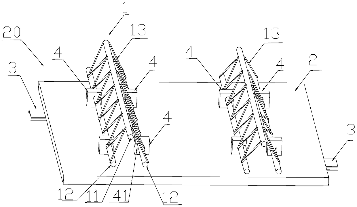
[0034] Such as figure 1 A detachable steel truss panel is shown, which includes a steel truss 1 , a connector 4 , a floor deck 2 and a support 3 . The steel bar truss 1 includes an upper chord steel bar 11 and two lower chord steel bars 12 , and the two lower chord steel bars 12 are respectively welded and connected to the upper chord steel bars 11 through web steel bars 13 . The two lower chord steel bars 12 are connected with the connecting piece 4 relative to each other. The connecting piece 4 includes a slot 41 through the connecting piece 4 with a side opening, and a threaded hole is provided at the lower end of the connecting piece 4 . The connectors 4 are clamped on the two lower chord steel bars 12 in pairs, and each pair of connectors 4 is arranged longitudinally on the steel bar truss 1 . figure 1 The length of the detachable steel truss plate 20 can be designed according to requirements, generally 1-3m, and its width is two steel trusses 2, and in some embodiments...

Embodiment 2

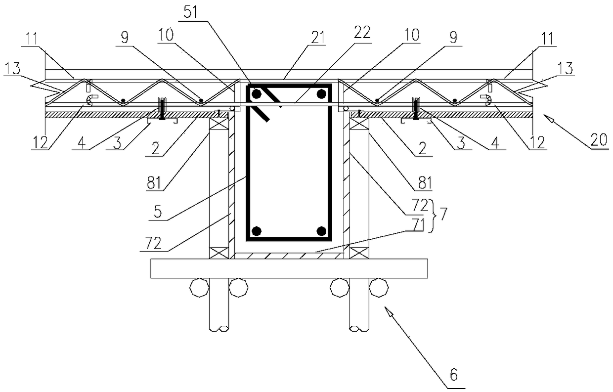
[0050] Such as Figure 7 As shown, the difference between this embodiment and Embodiment 1 is that the frame structure 5 is a frame wall, and formwork 7 is arranged on both sides of the frame wall, and the formwork 7 includes a side formwork 72 on the left side and a side formwork 72 on the right side, The outer side of the formwork is provided with a first support part, and the first support part 81 supports the steel bar truss plate 20 . Since the shear wall does not require the lower formwork, there is no need to erect a support frame.

Embodiment 3

[0052] Such as Figure 8-11 As mentioned above, the difference between this embodiment and Embodiment 1 is that the steel truss panels 20 on both sides of the frame structure 5 have a height difference, so that the forming surface of the upper part of the frame structure 5 and the sides of the frame structure 5 after pouring concrete Floor slabs have different elevations. The upper connecting rib 21 and the lower connecting rib 22 are provided with a first inclined portion 23 and a second inclined portion 24 respectively, and the first inclined portion 23 and the second inclined portion 24 can be located on the same side of the frame structure 5, It can also be the two sides of the frame structure 5 respectively. The first inclined portion 23 and the second inclined portion 24 enable the reinforced truss slabs 20 of different elevations to be well connected to the frame structure 5 , thereby making the poured concrete floor slabs firmly connected to the frame structure.

[0...


PUM


Abstract

The invention relates to the field of concrete structure building construction, in particular to an end supporting joint structure for steel bar truss plates crossing a frame structure. The end supporting joint structure comprises the frame structure, the steel bar truss plates, first supporting pieces and connecting bars, wherein the steel bar truss plates are located on the two sides of the frame structure. The steel bar truss plates comprise floor bearing plates, steel bar trusses detachably connected to one sides of the floor bearing plates, and supporting pieces arranged on the other sides of the floor bearing plates and protruding out of the floor bearing plates. A frame formwork is arranged on the outer side of the frame structure and comprises two side formworks, the floor bearingplates are arranged on one sides of the side formworks, and the upper ends of the side formworks and the upper surfaces of the floor bearing plates are equivalent in height. The first supporting pieces are provided with the ends for supporting the steel bar truss plates. The connecting bars penetrate through the frame structure to be connected with the ends of the steel bar trusses on the two sides of the frame structure in an overlapped mode. Hoisting and assembling of the steel bar truss plates are convenient and easy, the connecting bars are connected with the steel bar truss plates on thetwo sides of the frame structure, thus the connecting bars are easy and convenient to connect and easy to operate, and the joint portions of the formed floor bearing plates are level.

Description

technical field [0001] The invention relates to the field of concrete structure building construction, in particular to a steel bar truss plate spanning frame structure end support node structure. Background technique [0002] At present, horizontal structural formwork projects in my country's construction industry generally adopt bent frame support, supplemented by wooden squares and plywood or formwork. Its technological principle provides support for the bottom formwork by setting up a bent support system to meet the requirements of bearing capacity and deformation during the construction stage. [0003] Chinese patent application number: 2013102995081, patent name: self-supporting steel grid frame composite formwork and its construction method, discloses a steel grid frame composed of multiple rows of longitudinal steel trusses and multiple rows of horizontally distributed steel bars, and the steel grid frame and detachable The combination of formwork realizes the less-...

Claims


Application Information

Patent Timeline
Patent Type & Authority Applications(China)
IPC IPC(8): E04B1/38E04B5/16E04G11/48
CPCE04B1/38E04B5/16E04G11/48
Inventor 陈永德叶健
Owner ZHE JIANG ZHONGYI BUILDING MATERIALS TECH CO LTD
Why Eureka
Try Eureka