
An intelligent welding robot arm

A welding robot and arm technology, which is applied in the direction of manipulators, welding equipment, auxiliary welding equipment, etc., can solve the problems of reduced service life, uneven welding, and reduced work efficiency, so as to reduce the contact area, reduce the service life, and reduce work efficiency effect

Active Publication Date: 2020-11-20
LIAOCHENG YANGFINE JEONIL MACHINERY
View PDF6 Cites 0 Cited by
  • Summary
  • Abstract
  • Description
  • Claims
  • Application Information

AI Technical Summary

Problems solved by technology

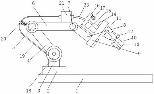
[0005] Aiming at the deficiencies of the prior art, the present invention provides an intelligent welding robot arm, which has the advantages of preventing sparks from spattering, facilitating welding wire reservation and less friction between the welding wire and the protective tube, etc. A large number of high-temperature sparks splashed out often "burn" the arm and pipeline of the robot, causing malfunction, reducing work efficiency and shortening the service life. Moreover, the welding wire supply of the welding robot only uses the reserved welding wire on the outside, which is easy to cause damage to the welding head. It curls and twists during multiple continuous rotations, which makes the welding wire bend, which is inconvenient for the welding of the welding head, thus reducing the welding quality of the automatic welding machine, and because the welding wire is always conveyed inside the protective tube, the welding wire and The frictional force generated by the contact between the protection tubes is large, which makes the welding uneven, thus reducing the problem of welding effect

Method used


Image

  • An intelligent welding robot arm
  • An intelligent welding robot arm
  • An intelligent welding robot arm

Examples


Embodiment Construction

[0029] The following will clearly and completely describe the technical solutions in the embodiments of the present invention with reference to the accompanying drawings in the embodiments of the present invention. Obviously, the described embodiments are only some, not all, embodiments of the present invention. Based on the embodiments of the present invention, all other embodiments obtained by persons of ordinary skill in the art without making creative efforts belong to the protection scope of the present invention.

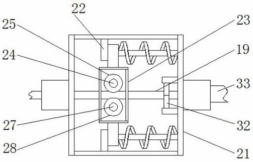
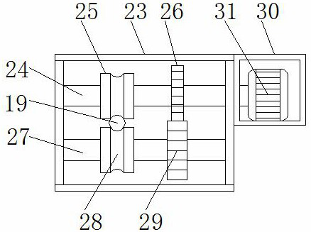
[0030] see Figure 1-7, the present invention provides a technical solution, an intelligent welding robot arm, including a support platform 1, a rotary joint 2 is fixedly installed on one side of the top of the support platform 1, a support column 3 is movably socketed in the middle of the rotary joint 2, and the support column 3 One side of the top is movably socketed with a lower bracket 4, the top of the lower bracket 4 is movably socketed with a revolving ...


PUM


Abstract

The invention relates to the field of intelligent welding robots, and discloses an intelligent welding robot arm. The intelligent welding robot arm comprises a supporting table. A rotary joint is fixedly mounted on one side of the top of the supporting table. The middle of an end face bearing is movably connected with a supporting column in a sleeved manner. One side of the top end of the supporting column is movably connected with a lower support in a sleeved manner. The top end of the lower support is movably connected with a rotating joint in a sleeved manner. According to the intelligent welding robot arm, a servo motor is driven by a power source to be started, meanwhile, an electromagnet is powered on to generate attraction force, the magnitude of the attraction force is controlled through a slide rheostat, and therefore the movement distance of an iron sheet is adjusted, and a protection cover moves and cannot interfere with the welding work of a welding joint; and meanwhile, sparks generated during welding are isolated by the protection cover, and the situation that during welding of an existing welding robot, arms and pipelines of a robot are frequently burnt by a large number of splashing high-temperature sparks, and failures are caused, the work efficiency is reduced, and the service life is shortened is avoided.

Description

technical field [0001] The invention relates to the field of intelligent welding robots, in particular to an intelligent welding robot arm. Background technique [0002] Welding robots are industrial robots used for automatic welding. Welding robots are widely used in repetitive and monotonous long-term operation scenarios in welding operations or welding operation scenarios in high-risk and harsh environments. They have the characteristics of high productivity, high quality and high stability. [0003] However, a large number of high-temperature sparks splashed out by existing welding robots during welding often "burn" the arms and pipelines of the robot, causing malfunctions, reducing work efficiency, and reducing service life. The external reservation is easy to curl and wind when the welding head rotates repeatedly, so that the welding wire is bent and the welding of the welding head is inconvenient, so that the welding quality of the automatic welding machine is reduce...

Claims


Application Information

Patent Timeline
Patent Type & Authority Patents(China)
IPC IPC(8): B23K37/00B23K37/02B25J11/00B25J19/00B25J19/06
CPCB23K37/00B23K37/006B23K37/02B25J11/005B25J19/00B25J19/06
Inventor 孙莉莉
Owner LIAOCHENG YANGFINE JEONIL MACHINERY
Learn More