Corn threshing device
A technology of corn threshing and threshing mechanism, which is applied in the direction of threshing equipment, cutters, agricultural machinery and implements, etc. It can solve the problems of increased labor costs, difficult transportation, and inadaptability to corn threshing, so as to achieve convenient shedding and ensure the threshing effect Effect
- Summary
- Abstract
- Description
- Claims
- Application Information
AI Technical Summary
Problems solved by technology
Method used
Image
Examples
Embodiment 1
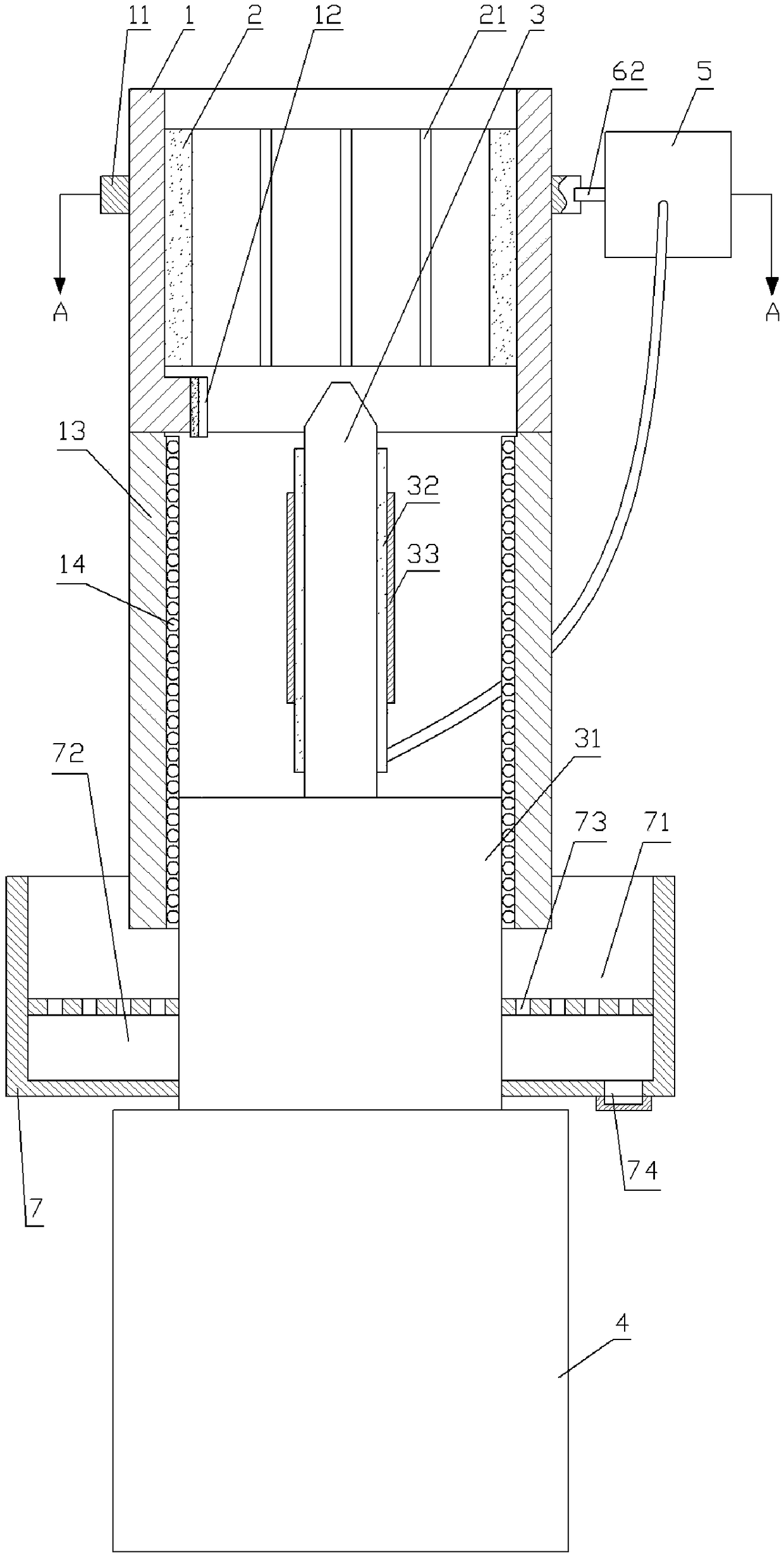
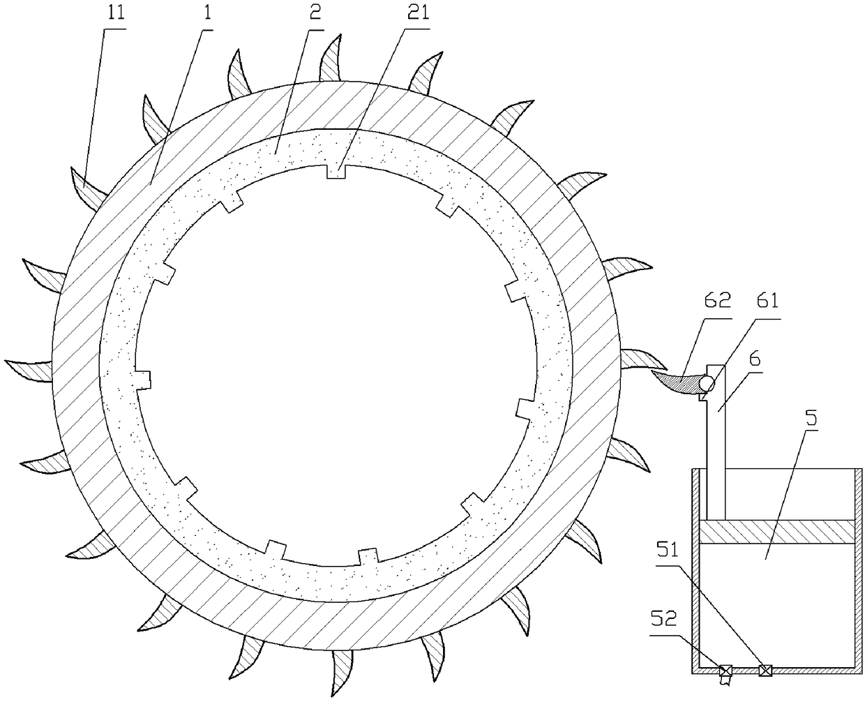
[0028] Corn threshing equipment, such as figure 1As shown, it includes a frame (not shown in the accompanying drawings), a threshing mechanism and a moving mechanism. The threshing mechanism includes a rotating drum 1, a slotting knife 12, a threaded part 13 and a threshing part 2, and the rotating drum 1 is arranged vertically. And it is rotatably connected with the frame, and the drum 1 can rotate relative to the frame. Slotting knife 12 and threaded part 13 are welded on the lower end of slotting knife 12, and the blade of slotting knife 12 is downward, and when corn cob passes through slotting knife 12, slotting knife 12 can cut corn cob along vertical direction, The corn kernels are shed and grooves are formed on the cob. The vertical projection of the slotting knife 12 in this embodiment is arc-shaped, which is convenient for the slotting knife 12 to be attached to the corn cob. The threshing part 2 is glued on the inner wall of the drum 1. The threshing part 2 in this...
Embodiment 2
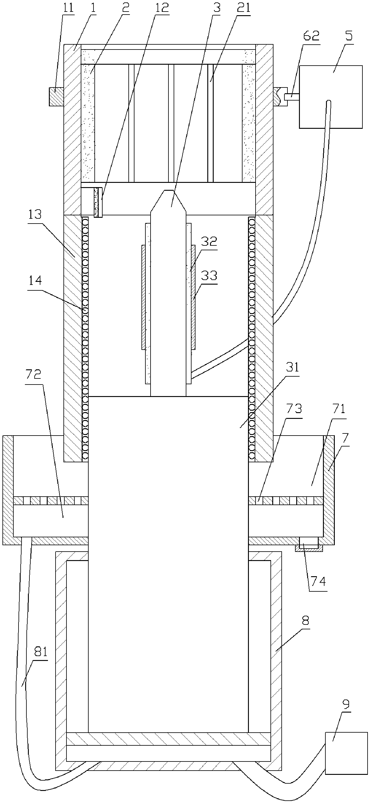
[0042] The difference from Example 1 is that, as image 3 As shown, the propulsion assembly in this embodiment includes an intake air pump 9 and an intake air cylinder 8 fixed on the frame, the intake air pump 9 communicates with the intake air cylinder 8 through a pipeline, and the intake air pump 9 can make the intake air cylinder The pressure in 8 increases, so the piston in the intake cylinder 8 can move upwards. The piston of the intake cylinder 8 is welded to the lower end of the threaded rod 3, and when the intake air pump 9 worked, the threaded rod 3 could move upwards.
[0043] The rodless chamber of the air intake cylinder 8 is communicated with a blowing pipe 81, and the upper end of the blowing pipe 81 is fixed on the bottom of the collection tank 7 and communicates with the collection tank 7 inner chambers. Because the pressure in the intake cylinder 8 increases, the gas in the intake cylinder 8 is discharged from the blowing pipe 81 simultaneously, forming an up...
PUM
 Abstract
Description
Claims
Application Information
 - R&D
- Intellectual Property
- Life Sciences
- Materials
- Tech Scout
- Unparalleled Data Quality
- Higher Quality Content
- 60% Fewer Hallucinations
Browse by: Latest US Patents, China's latest patents, Technical Efficacy Thesaurus, Application Domain, Technology Topic, Popular Technical Reports.
© 2025 PatSnap. All rights reserved.Legal|Privacy policy|Modern Slavery Act Transparency Statement|Sitemap|About US| Contact US: help@patsnap.com


