
Patsnap Eureka
For R&D, Patsnap Eureka makes reading and utilizing patents & technical documents easy.
Patsnap Eureka AIR
Designed for self-driven R&D workflows. Generate viable solutions, solve complex R&D challenges, empower your innovation with AI.

Patsnap Eureka Materials
Designed for material experts only. Revolutionize your material R&D, from search, analyze, to developing new materials.

TechResearch
Generate reliable direction feasibility study reports for your R&D in just a few steps.

TechSeek
Discover and master advanced knowledge NOW. Basics, ideas, possibilities, all at once.

TechMind
As an expert in R&D Theories, TechMind can generates customized viable solutions instantly.

TechRisk
Analyze your overall solution with one click, know your potential R&D risks in advance.

TechMonitor
Get weekly tech updates, stay abreast of the latest tech innovations and key insights.
Power assembly fault recording and diagnosis system and method
A technology for power components and fault recording, applied in measuring devices, instruments, measuring electricity and other directions, it can solve the problems of inability to accurately locate the cause of the fault, and the failure time cannot be reproduced, and achieve the effect of improving efficiency.
- Summary
- Abstract
- Description
- Claims
- Application Information
AI Technical Summary
Problems solved by technology
Method used
Image


Examples
Embodiment 1
[0054] as attached figure 1 As shown, a specific embodiment of a power component fault recording and diagnosis system includes: a power component 1 , and a control circuit 2 connected to the power component 1 .
[0055] As a typical specific embodiment of the present invention, the power assembly 1 adopts a three-phase bridge converter structure, and includes:
[0056] The power module 11, the power module 11 can be an IGBT module;
[0057] A voltage sensor 12 for collecting voltage signals of the power module 11;
[0058] A temperature sensor 13 for collecting a temperature signal of the power module 11;
[0059] and a current sensor 14 for collecting current signals of the power module 11;
[0060] And a radiator (not shown in the drawings) that provides heat dissipation for the power module 11;
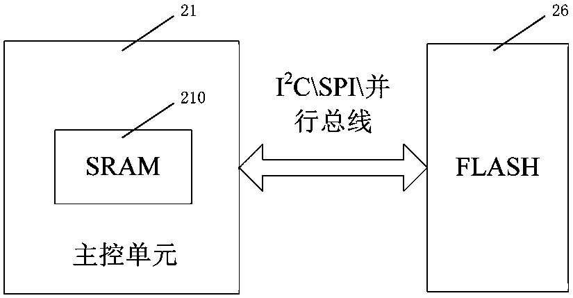
[0061] The control circuit 2 includes a main control unit 21, a sampling unit 22 connected to the main control unit 21, an interface unit 23 and a fault storage unit 26, which ...
Embodiment 2
[0073] A specific embodiment of a power component fault record diagnosis method based on the system described in the embodiment, comprising the following steps:
[0074] A) The voltage sensor 12 collects the voltage signal of the power module 11, the temperature sensor 13 collects the temperature signal of the power module 11, and the current sensor 14 collects the current signal of the power module 11;
[0075] B) The sampling unit 22 acquires the signals collected by the voltage sensor 12, the temperature sensor 13 and the current sensor 14 in real time, and sends the data to the main control unit 21;
[0076] C) The main control unit 21 reads the data sent by the sampling unit 22. When the main control unit 21 detects that the power component 1 has failed, it will record the voltage, temperature and current data of the power module 11 within a set time before and after the failure, and the fault State information and input PWM pulse data are saved to the fault storage unit ...
PUM
 Abstract
Description
Claims
Application Information
 - R&D Engineer
- R&D Manager
- IP Professional
- Industry Leading Data Capabilities
- Powerful AI technology
- Patent DNA Extraction
Browse by: Latest US Patents, China's latest patents, Technical Efficacy Thesaurus, Application Domain, Technology Topic, Popular Technical Reports.
© 2024 PatSnap. All rights reserved.Legal|Privacy policy|Modern Slavery Act Transparency Statement|Sitemap|About US| Contact US: help@patsnap.com