Capacitive voltage divider

A technology of capacitive voltage divider and voltage divider, which is applied in the direction of voltage divider, etc., can solve the problems of short service life and low safety factor, and achieve the effect of reducing influence, broad market prospect, and reducing sensor error

Inactive Publication Date: 2018-10-02
镇江盛创盈机电科技有限公司
View PDF0 Cites 2 Cited by
  • Summary
  • Abstract
  • Description
  • Claims
  • Application Information

AI Technical Summary

Problems solved by technology

At present, the capacitive voltage divider has the problems of low safety factor and short service life

Method used


Image

  • Capacitive voltage divider
  • Capacitive voltage divider

Examples


specific Embodiment approach

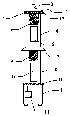
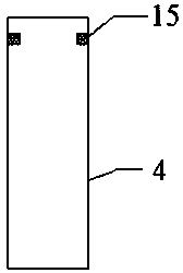
[0014] figure 1 Show the specific embodiment of the present invention: a kind of capacitive voltage divider, comprise base 1, wiring head 2, high voltage divider and low voltage divider, described high voltage divider is connected with wiring head 2 through high voltage pole plate 3, The high voltage divider includes a high epoxy sleeve 4, a high voltage expander 5 and a high voltage capacitor 6, the high voltage expander 5 and the high voltage capacitor 6 are arranged inside the high epoxy sleeve 4, the high pressure expander 5 It is connected with the high voltage capacitor 6 through a circuit, and the high voltage divider and the low voltage divider are connected through a connecting plate 7. The low voltage divider includes a low epoxy sleeve 8, a low voltage expander 9 and a low voltage capacitor 10. The low-voltage expander 9 and the low-voltage capacitor 10 are arranged inside the low epoxy sleeve 8, and the low voltage divider is connected to the base 1 through a low-v...


PUM


Abstract

The invention discloses a capacitive voltage divider. A lightning protection structure is arranged between a high voltage electrode plate and a wiring head, and therefore, the influence of lightning weather on the capacitive voltage divider can be decreased, and the use safety of workers can be improved; an optical voltage temperature sensing head is arranged in a base; sensor error can be reducedthrough using a self-healing compensation technology; round steel bars are arranged at two sides of the interior of a high epoxy sleeve; and after a high-pressure expander expands to a certain extent, the round steel bars will pierce the high-pressure expander, and therefore, the risk of the explosion of the high epoxy sleeve can be lowered. The capacitive voltage divider has the advantages of long service life, high safety factor, and bright market prospect.

Description

technical field [0001] The invention relates to the field of power devices, in particular to a capacitive voltage divider. Background technique [0002] Capacitive voltage divider, a voltage divider composed of capacitors. A component of a capacitive voltage transformer to which the primary voltage is applied. Capacitive voltage divider is mainly used in power frequency (50Hz or 60Hz) high-voltage power system to measure the output voltage (peak value, effective value, harmonic, etc.) of the test equipment, and can also be used as a coupling capacitor. Because the withstand voltage strength is higher than that of ordinary resistive voltage dividers, and it is not easy to break down, capacitive voltage dividers are generally used to measure AC high voltage. However, because the response time value of its frequency response effect is larger than that of the resistor divider, it is less used in the measurement of the impulse voltage than the resistor divider, and the resistan...

Claims


Application Information

Patent Timeline
Patent Type & Authority Applications(China)
IPC IPC(8): G01R15/06
CPCG01R15/06
Inventor 张涵
Owner 镇江盛创盈机电科技有限公司
Why Eureka
Try Eureka