
Double-roller valve body adjusting type electronic throttle valve

An electronic throttle and adjustable technology, which is applied in the direction of engine control, machine/engine, internal combustion piston engine, etc., can solve the problems such as the difficulty of precise control of the throttle of racing cars, the unstable operation of the throttle, and the unbalanced force of the valve plate, etc., to achieve Improve work efficiency and stability, improve work stability, smooth transmission effect

Inactive Publication Date: 2018-10-02
UNIV OF SHANGHAI FOR SCI & TECH
View PDF7 Cites 2 Cited by
  • Summary
  • Abstract
  • Description
  • Claims
  • Application Information

AI Technical Summary

Problems solved by technology

[0004] (1) There is a rotating shaft of the control valve plate in the middle of the air passage, the throttling loss is relatively large, and the air intake resistance is large, which affects the air intake efficiency;
[0005] (2) The valve plate of the traditional electronic throttle is impacted by a large air flow when the throttle valve is close to fully open, and the force on the valve plate is unbalanced, resulting in vibration of the valve plate, unstable operation of the throttle valve, and sluggish response;
[0006] (3) The response speed of the traditional mechanical valve plate throttle is slow, and the work is not linear, which makes it difficult to accurately control the throttle of the racing car;

Method used


Image

  • Double-roller valve body adjusting type electronic throttle valve
  • Double-roller valve body adjusting type electronic throttle valve
  • Double-roller valve body adjusting type electronic throttle valve

Examples


Embodiment

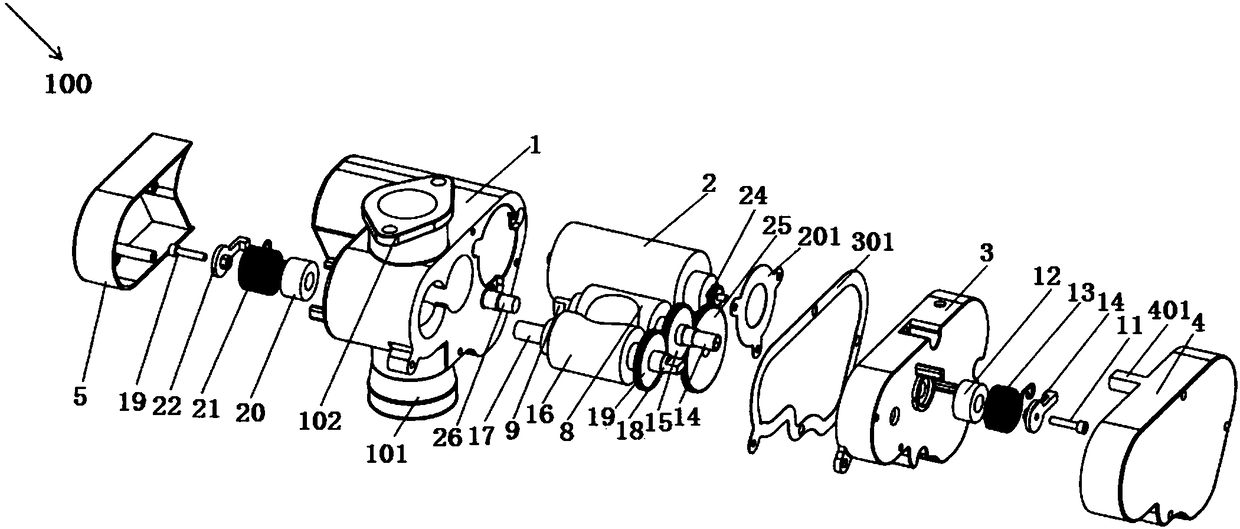
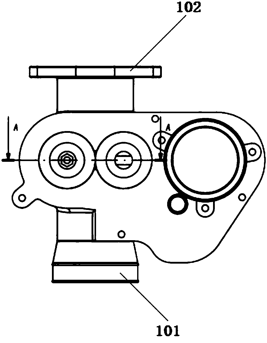
[0029] figure 1 It is a schematic diagram of the explosion of the dual-roller valve body adjustable electronic throttle in the embodiment of the present invention, figure 2 It is a side view of the structure of the dual roller valve body adjustable electronic throttle valve in the embodiment of the present invention.

[0030] Such as figure 1 and 2 As shown, a double-roller valve body adjustable electronic throttle 100 of this embodiment is used to control the intake air volume of a formula racing engine, and is characterized in that it includes: a throttle housing 1, a drum part, and a DC motor 2 , gear cover 3, front end cover 4 and rear end cover 5.

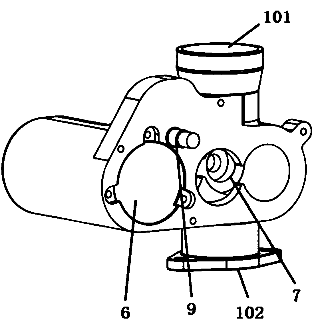
[0031] image 3 It is the left side view of the throttle housing of the double roller valve body adjustable electronic throttle in the embodiment of the present invention, Figure 4 It is a right side view of the throttle housing of the double roller body adjustable electronic throttle valve in the embodiment of the pres...


PUM


Abstract

The invention discloses a double-roller valve body adjusting type electronic throttle valve. The double-roller valve body adjusting type electronic throttle valve is used for controlling the air inletamount of an engine of a formula racing car. The electronic throttle valve comprises a throttle valve shell, a roller part and a direct-current motor; wherein the throttle valve shell is arranged onan air inlet system of the engine, an air inlet and an air outlet are formed in the throttle valve shell, wherein the air inlet is used for allowing air to enter, the air outlet is used for introducing the air entering from the air inlet into the engine, a direct-current motor mounting cavity and a roller valve mounting cavity are formed in the throttle valve shell, and the roller valve mounting cavity communicates with the air inlet and the air outlet; the roller part comprises a first roller assembly and a second roller assembly, and the first roller assembly and the second roller assembly are symmetrically arranged in the roller valve mounting cavity in opposite directions; and the direct-current motor is fixed in the direct-current motor mounting cavity through a direct-current motor check ring. The double-roller valve body adjusting type electronic throttle valve is simple in structure and convenient to install, and therefore time is saved, the throttling loss is effectively reduced, the air inlet efficiency is improved, and the working stability is further improved.

Description

technical field [0001] The invention relates to an electronic throttle, in particular to a dual-roller valve body adjustable electronic throttle. Background technique [0002] The throttle valve is a controllable valve installed in the engine intake pipe to control the intake air volume of the engine. After the gas passes through the throttle valve, it enters the intake pipe and mixes with gasoline to become a combustible mixture and enters the engine cylinder, thereby burning and doing work. According to the design rules, formula racing cars have restrictions on the diameter of the intake pipe. Generally, the diameter of the restrictor valve of the intake pipe is required to be no more than 20mm. In addition, Formula Student cars generally work under medium and high load conditions, and the throttle valve is fully open. It requires its throttle valve to respond quickly and have high intake efficiency. [0003] However, due to its own structural reasons, the traditional va...

Claims


Application Information

Patent Timeline
IPC IPC(8): F02D9/02F02D9/10F02D11/10
CPCF02D9/02F02D9/101F02D9/1065F02D9/109F02D11/10F02D2011/101Y02T10/12
Inventor 王小燕俞思豪王莹杰崔兴龙唐超张振东沈凯
Owner UNIV OF SHANGHAI FOR SCI & TECH
Learn More