Hand tool for hair removal by laser light

A hand tool and laser technology, which is applied in the fields of surgery, surgical instrument parts, medical science, etc., can solve the problems of easy damage to the surrounding skin tissue, the ineffective installation of the laser, and incomplete hair removal, so as to improve the quality of the laser and the efficiency of hair removal , Easy to clean, wipe and disinfect, unique and beautiful appearance

Pending Publication Date: 2018-10-02
北京凯尔斯科技开发有限公司
View PDF0 Cites 0 Cited by
  • Summary
  • Abstract
  • Description
  • Claims
  • Application Information

AI Technical Summary

Problems solved by technology

Although the existing hair removal instruments and hand tools can remove the roots, there are still many problems: 1. The appearance is bulky, and it is inconvenient to hold and operate; The process is complicated and the production speed is slow; 4. The laser cannot be installed effectively and is easily damaged; 5. The control range of the hair removal function area is not precise, and it is easy to damage the surrounding skin tissue or take off the hair that does not need to be removed by mistake, or the hair removal is not complete; 6. 1. The hair removal functional area directly contacts the outside world, easily polluted by dander and sundries, easily scratched or damaged, and affects the hair removal effect; 7. The area of ​​the hair removal functional area is small, and the hair removal is slow; 8. The pain in the hair removal area is strong, and the skin is prone to redness painful, unhygienic, susceptible to infection

Method used


Image

  • Hand tool for hair removal by laser light
  • Hand tool for hair removal by laser light
  • Hand tool for hair removal by laser light

Examples


Embodiment Construction

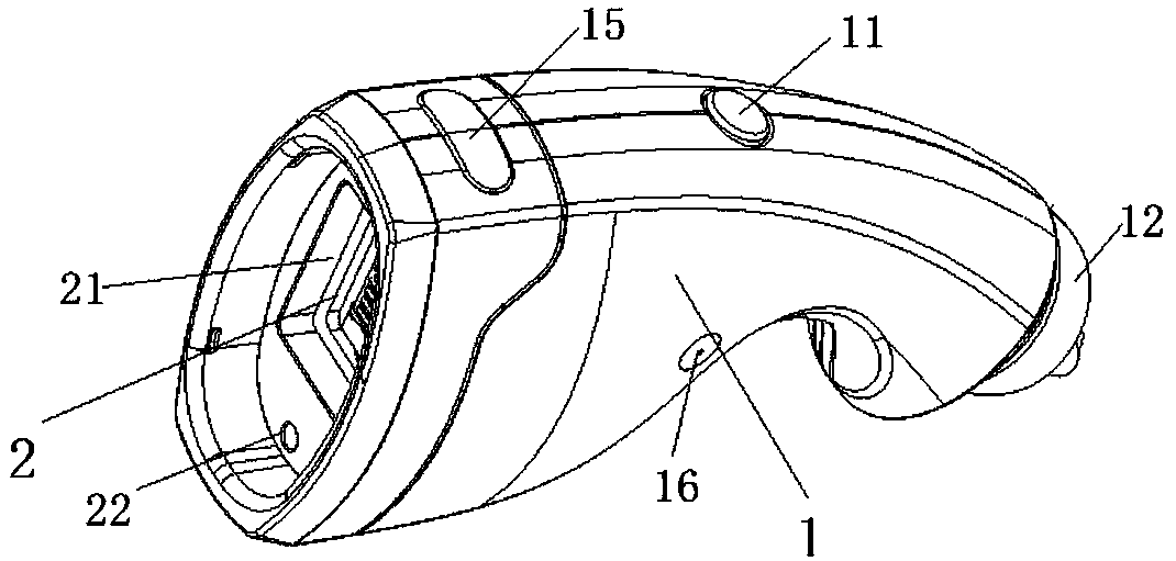
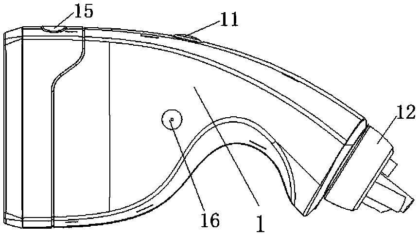
[0029] The invention relates to a laser hair removal hand tool, which comprises a hand tool shell and a hand tool core. The hand tool shell is a detachable structure with an open front end. Layer, laser and negative pressure channel, the laser emits light to the front through the light-transmitting layer, at least one negative pressure suction hole is arranged on the top of the ring structure, and the negative pressure suction hole is connected with the negative pressure channel. A vacuum negative pressure space is formed between the photolayer, the inner wall of the shell and the skin. The structure design of the laser hair removal hand tool is ingenious. Laser hair removal is carried out under the premise of forming a vacuum negative pressure space by setting negative pressure suction holes, negative pressure channels and specific structures. Using the combination of vacuum negative pressure technology and laser technology, the skin is instantly adsorbed to the hand. In the ...


PUM


Abstract

The invention relates to a hand tool for hair removal by laser light. The hand tool includes a hand tool housing and a hand tool core, the handle tool housing is of a detachable structure with an opening in the front end, and the handle core is disposed in the handle tool housing and includes an annular structure, a light transmitting layer, a laser device and a negative pressure channel; the laser device emits light to the front end through the light transmitting layer, at least one negative pressure suction hole is formed in the top of the annular structure and connected with the negative pressure channel, and during work, a vacuum negative pressure space is formed among the annular structure, the light transmitting layer, the inner wall of the housing and the skin. The structure designis ingenious, a vacuum negative pressure technology and a laser technology are used and combined, the skin is sucked into the opening of the front end of the hand tool housing instantly, vacuum negative pressure directly acts on the treated skin and instantaneously blocks transmission of pain information, the laser device instantaneously emits the laser light, and the laser light enters the subcutaneous tissue of the skin to destroy the black tissue of the hair, so that the effect of rapid and painless hair removal by the laser light is achieved without the need of injecting anesthetics in advance, the problem of cross infection is avoided, and meanwhile, the hair removal effect and hair removal efficiency are enhanced.

Description

technical field [0001] The invention relates to the technical field of household and medical beauty equipment, in particular to a laser hair removal hand tool. Background technique [0002] The surface of the human body is covered with hair. Abnormal hair growth or hirsutism may occur from time to time. It may be a symptom of hirsutism, or it may be caused by the use of certain drugs (such as male hormones). For people who pursue modern beauty Generally speaking, thick or redundant hair will make the image sloppy, greatly reduce the temperament, greatly affect the appearance, and it is very troublesome, so people will have the need to remove unwanted body hair to keep the appearance clean. For this reason, the current family Hair removal tools are often used in the and medical beauty industry. [0003] Traditional hair removal tools include tweezers, scrapers and the like. The operation of tweezers hair removal is simple, but tweezers hair removal is to pull out the hair b...

Claims


Application Information

Patent Timeline
Patent Type & Authority Applications(China)
IPC IPC(8): A61B18/20
CPCA61B18/20A61B2018/00011A61B2018/00476A61B2018/00595A61B2018/00702
Inventor 孙臣
Owner 北京凯尔斯科技开发有限公司
Why Eureka
Try Eureka