
Ultra wide band medium antenna

A medium antenna and ultra-wideband technology, which is applied in the field of radio communication terminal antennas, can solve the problems of heavy antennas, difficulty in meeting trend requirements, and difficulty in expanding bandwidth, etc., and achieves the effect of improving radiation bandwidth and impedance bandwidth.

Pending Publication Date: 2018-09-28
广东省安捷信通讯设备有限公司
View PDF6 Cites 2 Cited by
  • Summary
  • Abstract
  • Description
  • Claims
  • Application Information

AI Technical Summary

Problems solved by technology

On the premise that all the indicators of the antenna remain unchanged, the realization of miniaturized ultra-wideband puts forward higher requirements on the volume, profile, weight and cost of the antenna. Therefore, sheet metal units, die-casting units and conventional dielectric units are currently used. Manufactured antennas are difficult to meet the trend demand
For example, although the existing sheet metal unit or die-casting unit can meet 31.6% of the electrical bandwidth requirement in the 698-960MHz segment, it is limited by the characteristics of the metal material. After all, the size and weight make the antenna cumbersome, and it is difficult to meet the miniaturization requirements.
Although the size and weight of conventional dielectric antennas can be reduced, it is difficult to expand its bandwidth because the dielectric constant of the substrate is inversely proportional to the frequency bandwidth because of the non-metallic materials with different dielectric constants in the middle.

Method used


Image

  • Ultra wide band medium antenna
  • Ultra wide band medium antenna
  • Ultra wide band medium antenna

Examples


Embodiment Construction

[0034] The following will clearly and completely describe the technical solutions in the embodiments of the present invention with reference to the accompanying drawings in the embodiments of the present invention. Obviously, the described embodiments are only some, not all, embodiments of the present invention. Based on the embodiments of the present invention, all other embodiments obtained by persons of ordinary skill in the art without making creative efforts belong to the protection scope of the present invention.

[0035] The object of the present invention is to provide an ultra-wideband dielectric antenna to realize widening of bandwidth.

[0036] In order to make the above objects, features and advantages of the present invention more comprehensible, the present invention will be further described in detail below in conjunction with the accompanying drawings and specific embodiments.

[0037] The metal sheet metal unit is to cut and bend a copper or aluminum plate acc...


PUM


Abstract

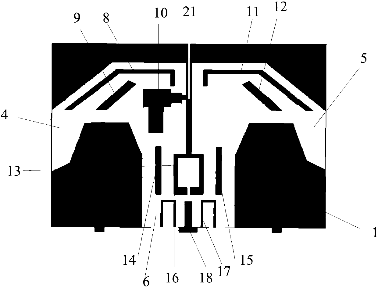
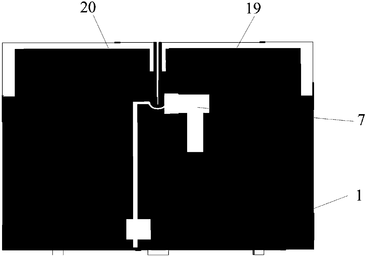
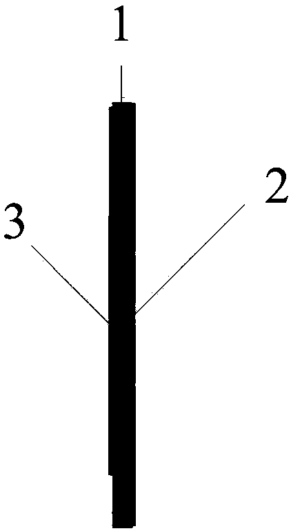
The invention discloses an ultra wide band medium antenna which comprises a medium layer, a first copper clad layer, a second copper clad layer, a first vibration arm, a second vibration arm, a Balun,a feeder, a first vibration arm gap, a second vibration arm gap and a third vibration arm gap. The first vibration arm gap, the second vibration arm gap and the third vibration arm gap are respectively formed on the first vibration arm; the first vibration arm gap comprises a first gap, a second gap and a third gap; the first gap is vertically connected with the second gap; the third gap is connected with the second gap and is at a certain obtuse angle with the second gap; the second vibration arm gap is in parallel to the third gap; the third vibration arm gap comprises a fourth gap, a fifthgap, a sixth gap and a seventh gap; the fourth gap is connected with the fifth gap; the sixth gap is connected with the fifth gap; and the seventh gap is connected with the sixth gap. According to the invention, the first vibration arm gap, the second vibration arm gap and the third vibration arm gap are respectively formed on the first vibration arm, so that a radiation band width and an impedance frequency band width of the medium antenna are improved.

Description

technical field [0001] The invention relates to the technical field of radio communication terminal antennas, in particular to an ultra-wideband dielectric antenna. Background technique [0002] In the field of radio communication terminal antennas, miniaturized ultra-wideband is one of the current development trends. On the premise that all the indicators of the antenna remain unchanged, the realization of miniaturized ultra-wideband puts forward higher requirements on the volume, profile, weight and cost of the antenna. Therefore, sheet metal units, die-casting units and conventional dielectric units are currently used. Manufactured antennas are difficult to meet trend demands. For example, although the existing sheet metal unit or die-casting unit can meet 31.6% of the electrical bandwidth requirement in the 698-960MHz segment, they are limited to the characteristics of the metal material. After all, the size and weight make the antenna cumbersome and difficult to meet t...

Claims


Application Information

Patent Timeline
Patent Type & Authority Applications(China)
IPC IPC(8): H01Q1/38H01Q1/50
CPCH01Q1/38H01Q1/50
Inventor 刘东峰王鲜富姚晓陈俊霖
Owner 广东省安捷信通讯设备有限公司
Learn More