
Wide Bandwidth Angular Scanning Phased Array Antenna Based on Flat Long Slot Antenna

A phased array antenna, wide-angle scanning technology, which is applied to antenna arrays, individually powered antenna arrays, antennas, etc. Active impedance fluctuation and other problems, to achieve the effect of simple structure, increased bandwidth, and increased operating bandwidth

Active Publication Date: 2020-01-14
UNIV OF ELECTRONICS SCI & TECH OF CHINA
View PDF5 Cites 0 Cited by
  • Summary
  • Abstract
  • Description
  • Claims
  • Application Information

AI Technical Summary

Problems solved by technology

However, in the state of strong mutual coupling, the strong mutual coupling effect of the antenna makes the state of large-angle scanning change greatly compared with that of side-firing, causing large fluctuations in its own active impedance, and it is difficult for the antenna to achieve large-angle scanning.
[0005] In summary, it is difficult for traditional phased array antennas to simultaneously have the capability of wide-band and wide-angle scanning, and the use of coupled strongly coupled dipole antenna arrays also has difficulty in large-angle scanning. The present invention is aimed at these key issues. propose

Method used


Image

  • Wide Bandwidth Angular Scanning Phased Array Antenna Based on Flat Long Slot Antenna
  • Wide Bandwidth Angular Scanning Phased Array Antenna Based on Flat Long Slot Antenna
  • Wide Bandwidth Angular Scanning Phased Array Antenna Based on Flat Long Slot Antenna

Examples


Embodiment 1

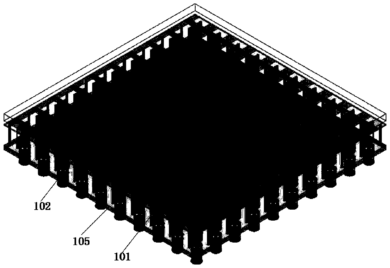
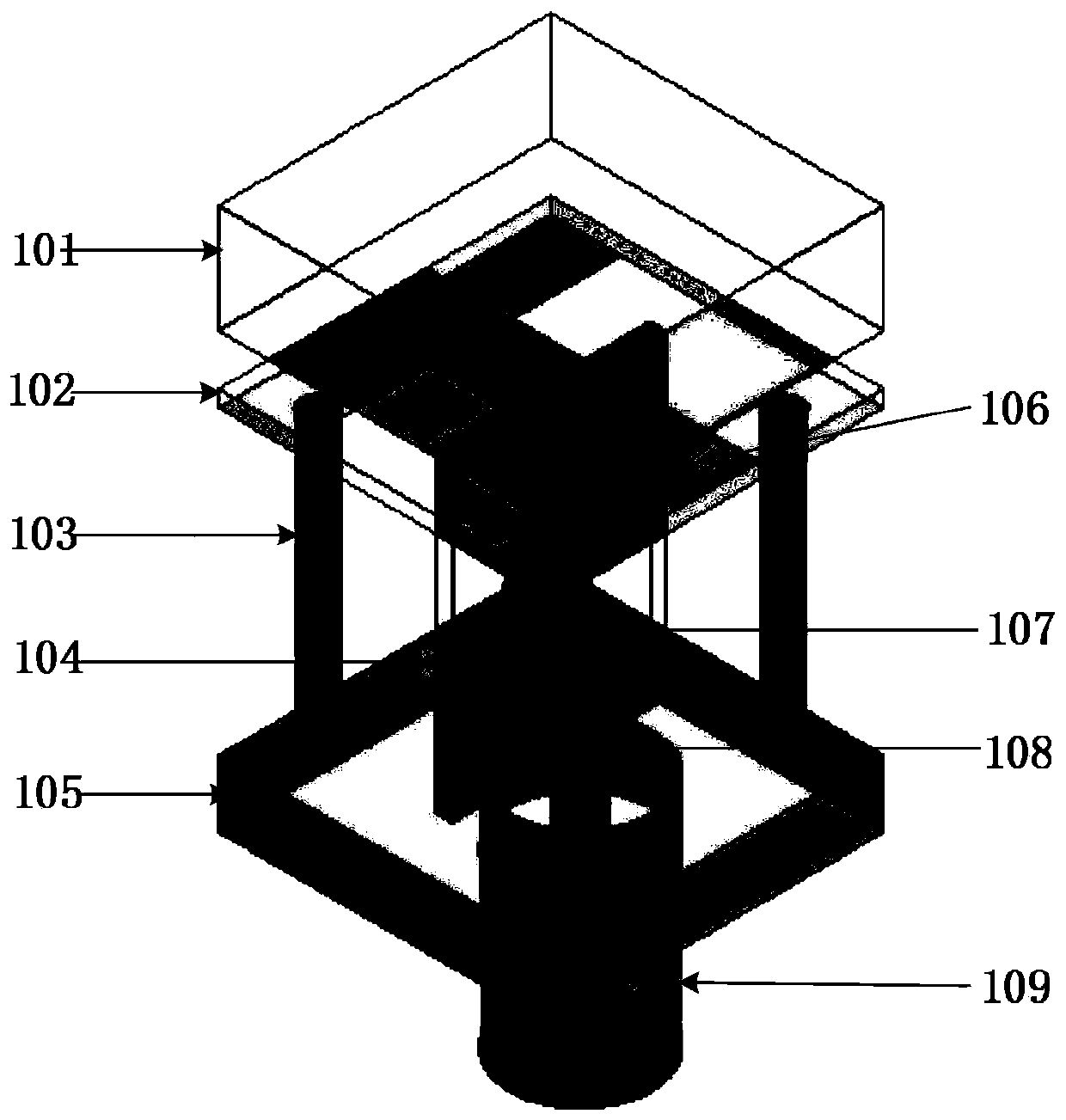
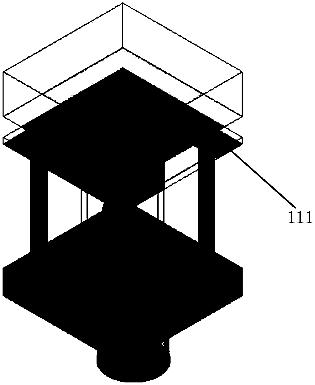
[0022] The wide bandwidth angular scanning phased array antenna based on the planar long slot antenna of this embodiment adopts a 10×10 planar array form, such as figure 1 As shown, it includes a lower metal floor 105, a vertical dielectric substrate 104 with microstrip gradient lines printed on both sides, a middle dielectric substrate 102 with metal patches printed on the upper and lower surfaces, a dielectric substrate 101 with a wide-angle matching function on the upper layer, and The metal probe 103 that is located above the diagonal line of the metal floor 105 and connects the metal patch 111 and the metal floor 105 plays a role of decoupling. Figure 2 shows figure 1 A schematic diagram of the basic antenna element. The lower metal floor 105 is an aluminum plate with a thickness of 2 mm. The relative dielectric constant of the vertical dielectric substrate 104 is 2.2, and the thickness is 0.254 mm. Microstrip gradient lines 107 and 112 are printed on both sides. One end...

Embodiment 2

[0026] Specifically, a planar array of any size can be formed by extending each basic antenna unit in a two-dimensional direction. Other structures are the same as those described in detail in Example 1.


PUM

PropertyMeasurementUnit
thicknessaaaaaaaaaa
thicknessaaaaaaaaaa
widthaaaaaaaaaa

Abstract

The invention discloses a wide bandwidth angle phased array antenna based on a flat plate slot antenna, which belongs to the field of radar technology and wireless communication. The antenna includes a lower metal floor, a middle dielectric substrate with metal patches printed on the upper and lower surfaces, and an upper dielectric substrate; a vertical dielectric substrate with microstrip gradient lines printed on both sides is arranged between the middle dielectric substrate and the metal floor, and a There are two metal probes. When the antenna array is working, the coaxial feed is fed to the microstrip gradient line, and then the metal patch on the lower surface of the middle dielectric substrate is coupled and fed to form a continuous current, which effectively increases the Working bandwidth. The metal probe ensures the large-angle scanning performance by reducing the mutual coupling between adjacent antenna elements, and increases the current loop to increase the resonance point, thereby increasing the bandwidth of the antenna. The invention realizes the wide-angle scanning of the broadband antenna, and has the advantages of simple structure, easy assembly and conformal integration.

Description

technical field [0001] The invention belongs to the technical fields of radar technology and wireless communication, and in particular relates to a wide-bandwidth angle-scanning phased array antenna based on a flat-panel slot antenna, which is suitable for radar and communication systems such as microwaves and millimeter waves. Background technique [0002] The phased array antenna is developed from the array antenna, and its basic principle is based on the analysis of the array antenna. The beam scanning of the phased array antenna is controlled by the computer to control the initial phase of the antenna unit, thereby controlling the wavefront position of the array antenna to achieve the beam scanning. Therefore, there is no inertia problem, and it has the advantages that conventional antennas do not have, such as fast scanning speed and fast beamforming, and has great flexibility. Phased array antennas are widely used in communication, radar, electronic countermeasures and...

Claims


Application Information

Patent Timeline
Patent Type & Authority Patents(China)
IPC IPC(8): H01Q1/38H01Q1/48H01Q1/50H01Q1/52H01Q21/06
CPCH01Q1/38H01Q1/48H01Q1/50H01Q1/523H01Q21/065
Inventor 屈世伟周吻亮张鹏遥肖林
Owner UNIV OF ELECTRONICS SCI & TECH OF CHINA
Learn More