
Graphics card mounting structure

A technology of installation structure and snap-fit ​​structure, applied in the direction of coupling device, parts of connecting device, connector of computer peripheral equipment, etc., can solve problems such as poor contact and inability to insert strip grooves

Inactive Publication Date: 2018-09-28
CHANGZHOU COLLEGE OF INFORMATION TECH
View PDF6 Cites 0 Cited by
  • Summary
  • Abstract
  • Description
  • Claims
  • Application Information

AI Technical Summary

Problems solved by technology

This kind of insertion installation structure is easy to be inserted because the opening of

Method used


Image

  • Graphics card mounting structure
  • Graphics card mounting structure
  • Graphics card mounting structure

Examples


Embodiment Construction

[0016] In order to facilitate the understanding of the invention, the invention will be described more fully below with reference to the associated drawings. Preferred embodiments of the invention are shown in the accompanying drawings. However, the invention can be embodied in many different forms and is not limited to the embodiments described herein. On the contrary, the purpose of providing these embodiments is to make the disclosure of the invention more thorough and comprehensive.

[0017] It should be noted that when an element is referred to as being “fixed” to another element, it can be directly on the other element or there can also be an intervening element. When an element is referred to as being "connected to" another element, it can be directly connected to the other element or intervening elements may also be present. The terms "vertical," "horizontal," "left," "right," and similar expressions are used herein for purposes of illustration only and are not inten...


PUM


Abstract

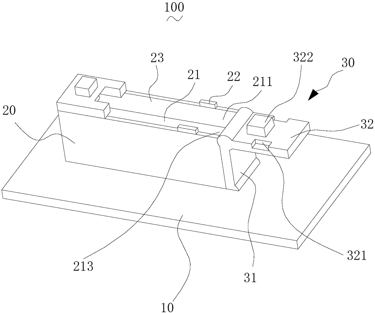
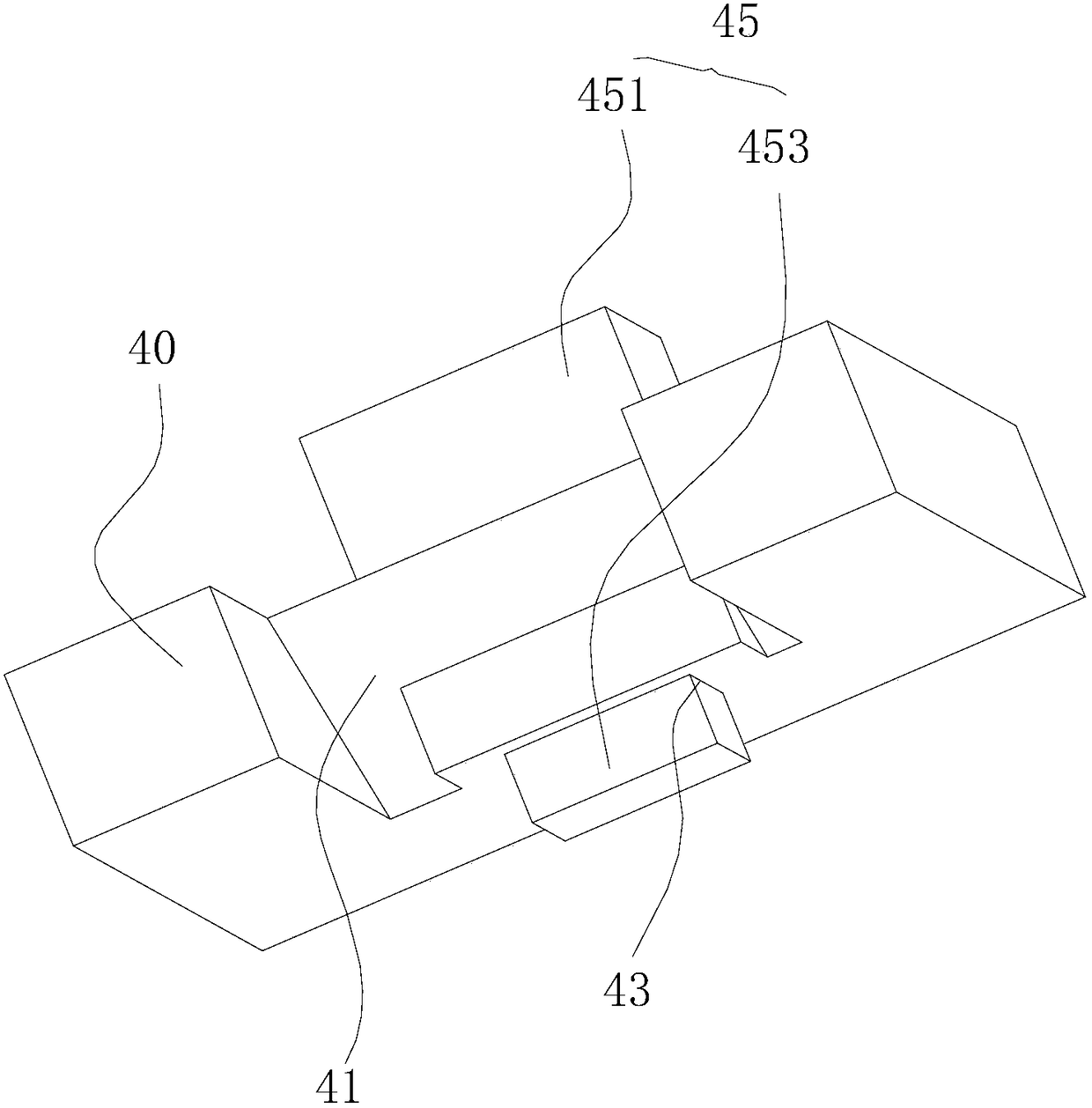
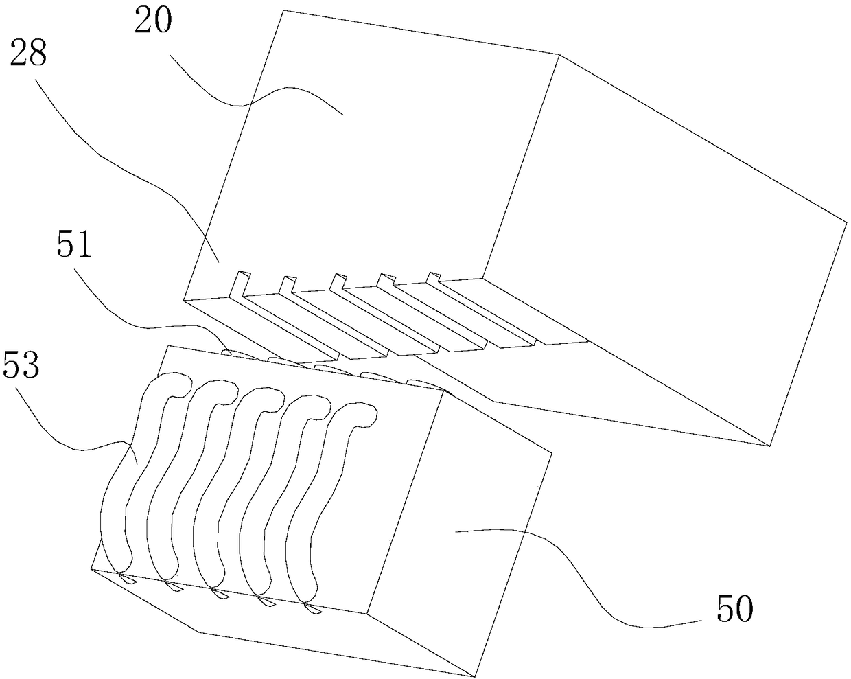
The invention relates to a graphics card mounting structure. The graphics card mounting structure comprises a bottom plate, a mounting base and a clamping structure, wherein the bottom plate is arranged in a mainframe box body; the mounting base is convexly arranged on the bottom plate; an insertion slot for accommodating a graphics card is formed in the mounting base; a clamping bulge is convexlyformed in the end part of the mounting base; a plurality of electric contact points are arranged at the bottom end of the insertion slot; guiding inclined surfaces are respectively formed on the twosides of the top part of the insertion slot; one end of the insertion slot penetrates through the mounting base so as to form an opening; the clamping structure is arranged at the opening of the insertion slot; and the clamping structure comprises a rotating bar and a clamping piece. According to the graphics card mounting structure disclosed by the invention, the graphics card is successfully mounted, and good electric connection between the graphics card and the mainframe box body is ensured.

Description

technical field [0001] The invention relates to a graphics card installation structure. Background technique [0002] The existing graphics card installation structure generally adopts a bar-shaped slot structure, that is, the video card is inserted into the bar-shaped slot, thereby completing the insertion and installation of the video card. This insertion installation structure is likely to be unable to be inserted because the opening of the strip groove is too small, and it is easy to cause poor contact after repeated insertion. Contents of the invention [0003] Based on this, it is necessary to provide a graphics card installation structure with smooth insertion and good contact. [0004] A graphics card installation structure, including a bottom plate, a mounting seat and a snap-fit ​​structure, the bottom plate is arranged in a mainframe box, the mounting seat is protruded on the bottom plate, and an insertion slot is formed on the mounting seat to accommodate a gr...

Claims


Application Information

Patent Timeline
IPC IPC(8): G06F1/18H01R12/72H01R13/639H01R13/502
CPCG06F1/183H01R12/721H01R13/502H01R13/639H01R2201/06
Inventor 权小红
Owner CHANGZHOU COLLEGE OF INFORMATION TECH
Learn More