
Lamp part connecting structure

A technology for connecting structures and components, which is applied in the field of connecting structures for lamp components, and can solve problems such as breakage of protrusions

Active Publication Date: 2016-08-17
KOITO MFG CO LTD
View PDF4 Cites 0 Cited by
  • Summary
  • Abstract
  • Description
  • Claims
  • Application Information

AI Technical Summary

Problems solved by technology

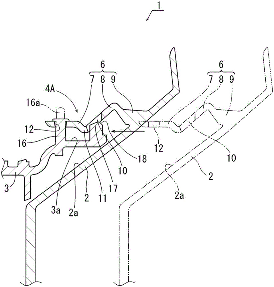
[0006] However, as described above, when the mounting portion of the first component is brought close to the protruding portion from the side of the protruding portion of the second component, and the front end of the mounting portion pushes the side portion of the protruding portion as the mounting portion advances ( When the protrusion is deflected), when the deflection exceeds the elastic limit of the protrusion, the protrusion may be broken

Method used


Image

  • Lamp part connecting structure
  • Lamp part connecting structure
  • Lamp part connecting structure

Examples


Embodiment Construction

[0040] Embodiments of the present invention will be described below with reference to the drawings. In the following embodiments, various limitations are made on constituent elements, types, combinations, shapes, relative arrangements, etc., but these are merely examples, and the present invention is not limited thereto.

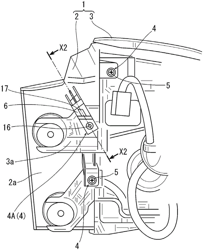
[0041] exist figure 1 Among them, symbol 1 is a vehicle lamp. A vehicle lamp 1 includes a resin-made bezel 2 as a first component, and a resin-made lamp body 3 as a second component. The connecting part 4 connects the light shielding plate 2 and integrates it.

[0042] At two of the plurality of connecting parts 4, the visor 2 and the lamp body 3 are connected by using the stopper 5, and on the other hand, at the connecting part 4A, which is one of the plurality of connecting parts 4, the light shielding plate 2 and the lamp body 3 are connected by using heat The shading plate 2 and the lamp body 3 are connected by riveting.

[0043] In the above connect...


PUM


Abstract

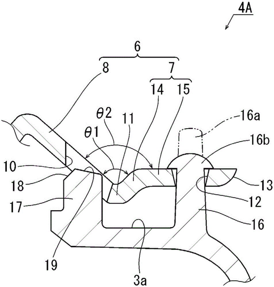
The invention relates to a lamp part connecting structure; the lamp part connecting structure allows a first part mounting portion to approach a protrusion portion through the side portion of a second part protrusion portion without breaking the protrusion portion, and can accurately insert the protrusion portion into a mount hole of the mounting portion; a shield plate (2) and the lamp body (3) are connected; the shield plate is provided with the flexible mounting portion (6) and mount hole (12); the lamp body (3) comprises the protrusion portion (16) and a guide portion (17); when the front end of the mounting portion (6) is positioned by the guide portion (17) of the protrusion portion (16) and the mounting portion (6) presses against the guide portion (17), the guide portion (17) can bend the mounting portion (6), so the front end of the mounting portion (6) can face the outer side of the front end of the protrusion portion (16).

Description

technical field [0001] The invention relates to a connection structure of lamp components. Background technique [0002] In the connecting structure of lamp parts, there is a structure as follows: for example, as shown in Patent Document 1 (FIG. 9), a mounting hole is provided in the mounting part of the first part, and on the other hand, a mounting hole is provided in the second part. There is a protrusion, and by inserting the protrusion of the second member into the mounting hole of the first member, the protrusion is held in the mounting hole by utilizing the properties of the protrusion (thermal caulking using thermal deformation in Patent Document 1). When manufacturing such a connection structure, in the axial direction of the protrusion in the second member, by arranging the first member and the second member at a position separated by a necessary distance, one of the first member and the second member and The other side approaches so that the protrusion of the seco...

Claims


Application Information

Patent Timeline
IPC IPC(8): F21S8/10F21V17/10F21W101/02F21W107/10
CPCF21S43/00F21V17/10F21W2107/10
Inventor 户崎隆太郎菅沼田晋也
Owner KOITO MFG CO LTD
Learn More