
Soil particle size separation device and separation method thereof

A separation device and soil particle technology, applied in the field of soil erosion and soil environmental monitoring, can solve the problem of radionuclide content determination and analysis, and overestimation of soil samples with different particle sizes that rarely consider radionuclide adsorption. Erosion amount and other issues, to achieve the effect of accurate separation, accurate separation and collection, and easy operation

Inactive Publication Date: 2018-09-28
BEIJING NORMAL UNIVERSITY
View PDF6 Cites 0 Cited by
  • Summary
  • Abstract
  • Description
  • Claims
  • Application Information

AI Technical Summary

Problems solved by technology

At present, in the application of the calculation model, the adsorption status of radionuclides in different particle sizes is rarely considered. The default is that there is no difference in the nuclide content of soil particles with different particle sizes in the sample, but the process of soil erosion and sediment deposition Among them, soil particles with different particle sizes behave differently. Fine particles are easier to be stripped and transported than coarse particles, while coarse particles are easier to deposit.
A large number of previous experiments have also shown that radionuclides, nutrients, and heavy metals are more likely to be adsorbed in soil clay, and the current calculation model may overestimate the amount of erosion
However, few people have studied the adsorption capacity of different particle sizes. This research is mainly limited by the soil particle size classification method, and it is impossible to obtain soil samples with different particle sizes for the determination and analysis of radionuclide content.

Method used


Image

  • Soil particle size separation device and separation method thereof
  • Soil particle size separation device and separation method thereof
  • Soil particle size separation device and separation method thereof

Examples


Embodiment Construction

[0025] Exemplary embodiments, features, and aspects of the present invention will be described in detail below with reference to the accompanying drawings. The same reference numbers in the figures indicate functionally identical or similar elements. While various aspects of the embodiments are shown in drawings, the drawings are not necessarily drawn to scale unless specifically indicated.

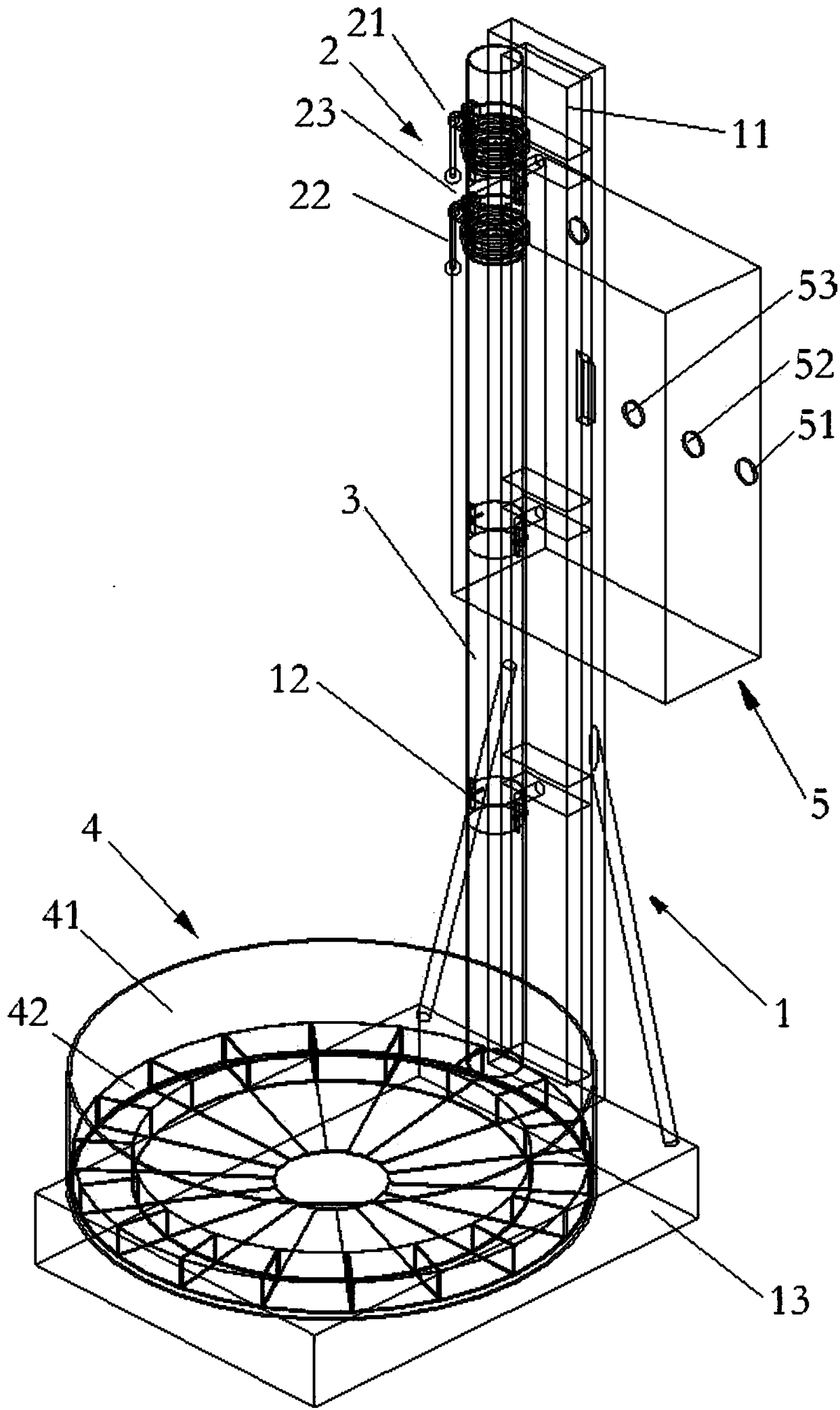
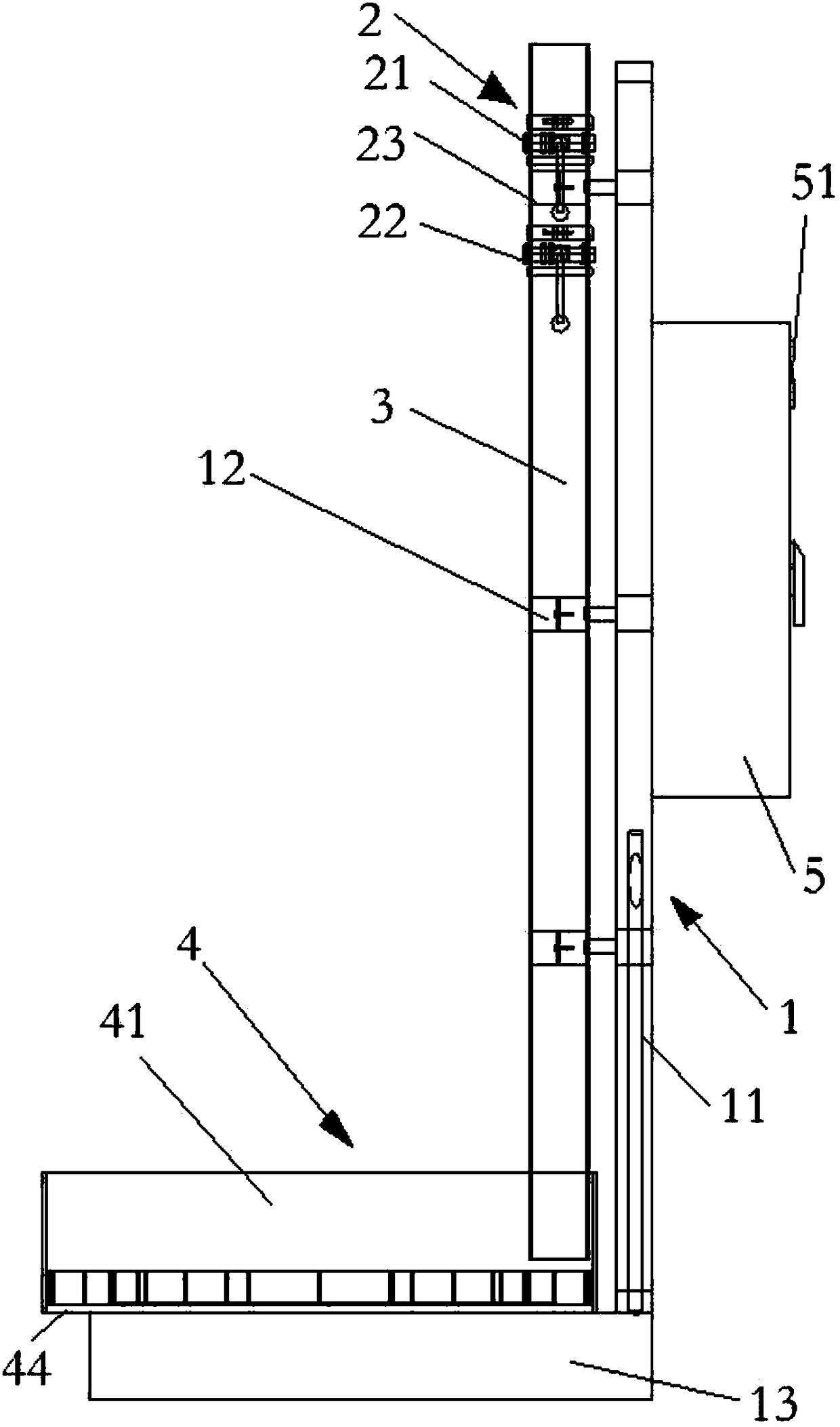
[0026] like Figure 1-2 As shown, the soil particle size separation device of the present invention includes a support 1, an injection device 2, a settling tube 3, a turntable 4 and a control box 5, and the support 1 includes a column 11, a claw 12 vertically arranged with the column 11, and a base 13 And a plurality of pillars (not shown) that are evenly arranged on the base 13, an electric motor is fixed on the pillar, a tray 44 with a bearing is connected to the upper end of the pillar, and a plurality of claws 12 hold the injection device 2 and the settling tube tightly respectively ...


PUM

PropertyMeasurementUnit
lengthaaaaaaaaaa

Abstract

The invention belongs to the technical field of soil erosion and soil environment monitoring, and relates to a soil particle size separation device. The soil particle size separation device comprisesa support, an injection device, a sedimentation pipe, a rotary disc and a control box, wherein the support comprises an upright post, enclasping claws, a base and a plurality of support columns arranged on the base; an electric motor is fixedly arranged on the support columns; the upper ends of the support columns are connected with a tray provided with a bearing; the plurality of enclasping clawsare used for respectively enclasping the injection device and the sedimentation pipe; the injection device comprises a first spherical valve, a second spherical valve and a central cavity; the firstspherical valve is positioned on the upper part of the second spherical valve; the upper part of the sedimentation pipe is fixedly connected with the central cavity of the injection device; a detachable sealing valve is arranged on the bottom of the sedimentation pipe; the lower part of the sedimentation pipe extends into the rotary disc; the rotary disc comprises a rotary disc body and a samplingdisc; the bottom part of the rotary disc body is positioned on a bearing of the tray; the tray can be driven by the electric motor to rotate around a central shaft; the control box comprises a main switch, a speed control module and a time control module, and the control box is electrically connected with the electric motor.

Description

technical field [0001] The invention belongs to the technical field of soil erosion and soil environment monitoring, and relates to a soil particle size separation device and a separation method thereof. Background technique [0002] As land degradation on a global scale has increasingly become the main obstacle to the sustainable development of human society, the research on soil erosion and land degradation caused by soil erosion is becoming more and more important. The research and estimation of soil erosion can be used for effective monitoring and management of soil Erosion provides a basis for rational allocation of soil and water conservation measures and provides guidance for water and soil conservation planning. The application of radionuclide tracer technology in soil erosion research began to develop from the research on the relationship between soil erosion and radionuclide deposition and transport in the early 1960s. The basic principle of radionuclide tracer is...

Claims


Application Information

Patent Timeline
Patent Type & Authority Applications(China)
IPC IPC(8): G01N1/38
CPCG01N1/38
Inventor 魏欣胡亚鲜刘瑛娜刘宝元
Owner BEIJING NORMAL UNIVERSITY
Learn More