


Quick Research
Generate reliable direction feasibility study reports for your R&D in just a few steps.

Technical Q&A
Discover and master advanced knowledge NOW. Basics, ideas, possibilities, all at once.

Find Solutions
As an expert in R&D theories, this can generate solutions to your technical problems instantly.

Evaluate Feasibility
Analyze your overall solution with one click, know your potential R&D risks in advance.

Monitor Landscape
Get weekly tech updates, stay abreast of the latest tech innovations and key insights.
Rotor local thermal stress unevenness monitoring method of steam turbine in low load working condition
A steam turbine and thermal stress technology, which is applied to mechanical equipment, engine components, engine functions, etc., can solve problems such as uneven thermal stress
- Summary
- Abstract
- Description
- Claims
- Application Information
AI Technical Summary
Problems solved by technology
Method used
Image


Examples
specific Embodiment approach 1
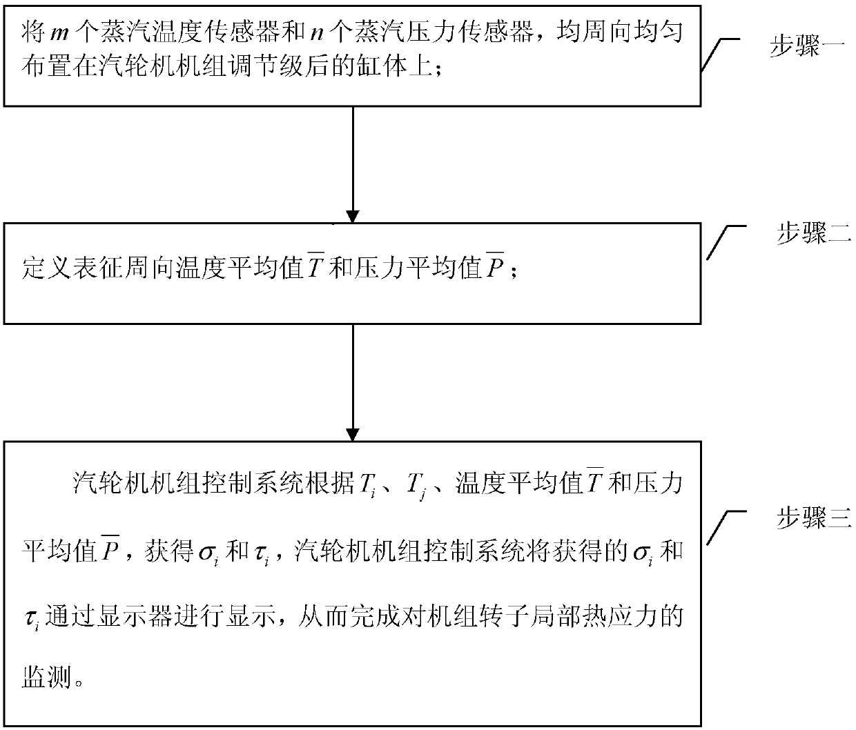
[0031] Specific implementation mode one: see figure 1 Describe this embodiment, a method for monitoring the non-uniformity of thermal stress in the rotor under the low-load condition of a steam turbine described in this embodiment, the method includes the following steps:
[0032] Step 1. Arranging m steam temperature sensors and n steam pressure sensors evenly in the circumferential direction on the cylinder block after the adjustment stage of the steam turbine unit; where m and n are integers,
[0033] Step 2. Define and characterize the average circumferential temperature and pressure average
[0034]
[0035]
[0036] T i Indicates the steam temperature detected by the i-th steam temperature sensor, T j Indicates the steam pressure detected by the jth steam pressure sensor, i and j are both positive numbers;
[0037] Step 3, the control system of the steam turbine unit according to T i , T j , average temperature and pressure average get σ i and τ i , ...
specific Embodiment approach 2
[0044] Specific implementation mode two: see figure 1This embodiment is described. The difference between this embodiment and the method for monitoring the non-uniformity of thermal stress in the rotor under low-load conditions of a steam turbine described in Embodiment 1 is that the value range of n is n≥2.
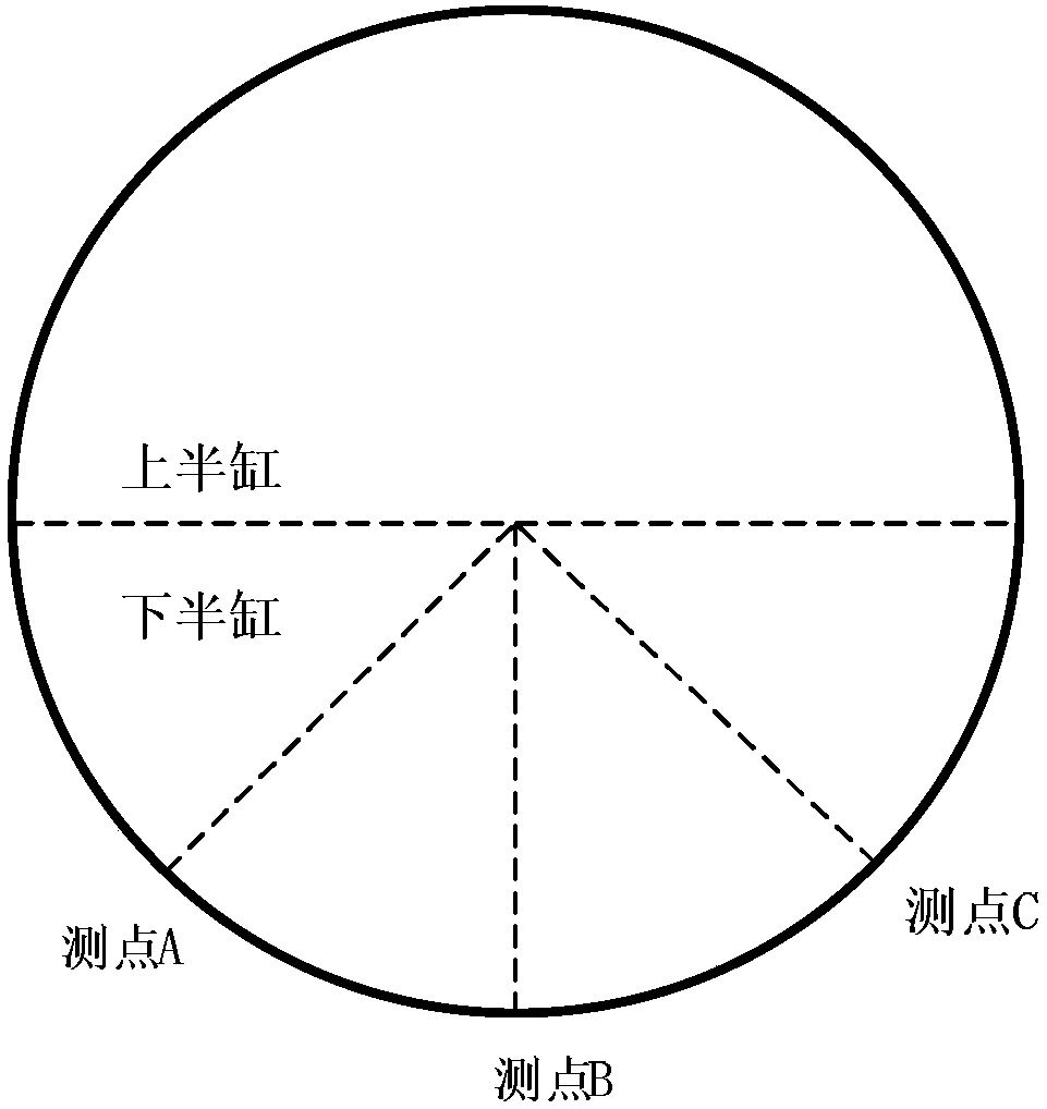
[0045] In this embodiment, figure 2 Among them, measuring points A and C are the measuring points of steam temperature after adjustment: both inner and outer cylinders are drilled through, and the thermocouple is fixed with a sleeve. The pipe is led out and connected to the pressure transmitter.
[0046] The optimized layout of measuring points can add temperature and pressure measuring points according to the existing position. The installation position of the measuring points adopts the principle of axisymmetric distribution of measuring points of the same parameter, and the number of measuring points is increased from the original to 8, such as image 3 shown. Amo...
specific Embodiment approach 3
[0047] Specific implementation mode three: see figure 1 This embodiment is described. The difference between this embodiment and the method for monitoring the local thermal stress non-uniformity of the rotor under the low-load condition of a steam turbine described in Embodiment 1 is that the value range of m is m≥2.
PUM
 Abstract
Description
Claims
Application Information
 - R&D Engineer
- R&D Manager
- IP Professional
- Industry Leading Data Capabilities
- Powerful AI technology
- Patent DNA Extraction
Browse by: Latest US Patents, China's latest patents, Technical Efficacy Thesaurus, Application Domain, Technology Topic, Popular Technical Reports.
© 2024 PatSnap. All rights reserved.Legal|Privacy policy|Modern Slavery Act Transparency Statement|Sitemap|About US| Contact US: help@patsnap.com