
Simple safety valve shield for stand column

A safety valve and shield technology, which is applied to pillars/supports, mining equipment, earth-moving drilling, etc., can solve the problems of affecting the strength of the cylinder block, increase the cost, complex structure, etc., achieve simple structure, convenient installation and disassembly, and reduce costs. Effect

Pending Publication Date: 2018-09-28
CHINA COAL BEIJING COAL MINING MACHINERY
View PDF8 Cites 0 Cited by
  • Summary
  • Abstract
  • Description
  • Claims
  • Application Information

AI Technical Summary

Problems solved by technology

[0007] The lug plate needs to be welded on the shield, resulting in a complicated structure;
[0008] A valve backing plate needs to be installed on the column, which increases the cost;
[0009] The valve backing plate is welded on the column, and the welding heat affects the strength of the cylinder block

Method used


Image

  • Simple safety valve shield for stand column
  • Simple safety valve shield for stand column
  • Simple safety valve shield for stand column

Examples


specific Embodiment approach

[0023] The preferred embodiment of the simple column safety valve shield of the present invention is:

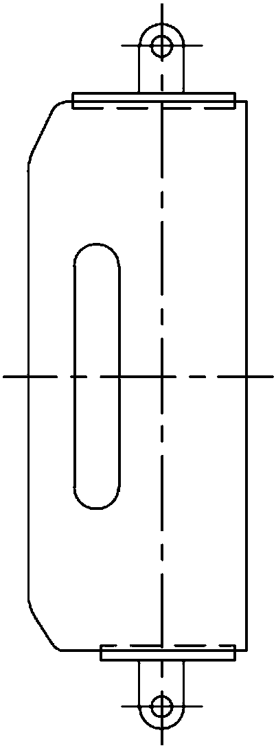
[0024] The shield consists of a channel structure made of thin-walled steel plates surrounded by three sides and open on one side. The upper end of the channel structure is sealed and the lower end is open. Corresponding small holes are provided on the opposite sides of the channel structure. , There is a fixing piece in the small hole.

[0025] The fixing part is any one of the following: cotter pin, U-shaped card, B-shaped pin, bolt and nut, steel bar, steel bar.

[0026] After the safety valve is installed on the column, buckle the guard cover, and put a fixing piece in the small hole to realize the fixing of the guard cover.

[0027] The fixing part is installed under the valve seat of the safety valve.

[0028] The simple column safety valve shield of the present invention does not need ear plates on the shield, has a simple structure and a smooth shape; only cotter p...

specific Embodiment

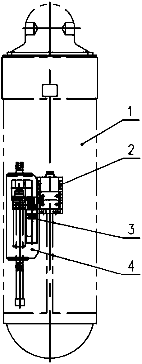
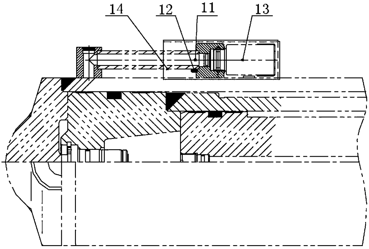
[0029] like image 3 , Figure 4 , Figure 5 As shown, the shield of the simple safety valve is made of thin-walled steel plate, and there is no lug plate on the shield, so the structure is simple. Small holes are machined on the guard for passing the cotter pins. After the column safety valve is installed on the column, fasten the safety valve guard and put on the cotter pin to complete the fixing of the guard.

[0030] After the shield is buckled on the safety valve, it is necessary to ensure that the cotter pin hole is under the safety valve seat of the column, so that the cotter pin can play the role of fixing the shield.

[0031] The beneficial effects brought by the technical solution of the present invention:

[0032] The simple safety valve shield has a simple structure and low processing cost;

[0033] There is no need to weld accessories on the column to avoid the influence of welding on the strength of the column;

[0034] The simple guard is easy to install a...


PUM


Abstract

The invention discloses a simple safety valve shield for a stand column. The simple safety valve shield comprises a thin-wall steel sheet groove shaped structure with three sides enclosed and one sideopen; the upper end of the groove structure is sealed and the lower end of the groove structure is opened; corresponding small holes are formed in opposite lateral sides of the groove structure; andthe small holes are provided with cotter pins or other fixing pieces in a penetrating mode. When the safety valve is mounted at the stand column, the shield is fastened; and the small holes are penetrated by the fixing pieces and the shield is fixed. The fixing pieces are mounted under a valve seat of the safety valve. The shield is free of a lug plate. The structure is simple and the outline is smooth; only the cotter pins are needed to fix between the shield and the stand column, installation and disassembly are convenient; the stand column is free of welding a valve pad, and therefore the cost is lowered and influence on a cylinder intensity is avoided.

Description

technical field [0001] The invention relates to a hydraulic support column for coal mines, in particular to a simple column safety valve shield. Background technique [0002] In order to avoid damage and failure of the oil cylinder after being overloaded on the hydraulic support, it is necessary to install a safety valve on the side with higher pressure of the oil cylinder. The safety valve is set to a certain pressure value when it leaves the factory. When the cylinder pressure exceeds the set pressure value, the safety valve unloads and reduces pressure. In the application, when the hydraulic support bears the pressure of the roof, the pressure in the lower cavity of the column cylinder is relatively high. In order to protect the column, a safety valve needs to be installed in the lower cavity of the column. [0003] like figure 1 As shown, in the prior art, a U-shaped clip is used to fix the column safety valve and the column joint seat. Due to the harsh environment of...

Claims


Application Information

Patent Timeline
Patent Type & Authority Applications(China)
IPC IPC(8): E21D15/51
CPCE21D15/512
Inventor 姜伟甄亚东陈井龙于永胜
Owner CHINA COAL BEIJING COAL MINING MACHINERY
Learn More