Drill bit for construction of cast-in-situ bored pile

A technique for drilling cast-in-place piles and drill bits, which is applied in directional drilling, construction, etc., and can solve the problems of not having much effect on finding the center and positioning, not obvious help in finding the center and positioning, and poor slag discharge, etc., so as to improve drilling efficiency. Improve the feeding efficiency and the service life of the drill bit, ensure the smooth reverse circulation, and avoid the effect of drilling slag congestion

Pending Publication Date: 2018-09-28
浙江易通特种基础工程股份有限公司
View PDF0 Cites 2 Cited by
  • Summary
  • Abstract
  • Description
  • Claims
  • Application Information

AI Technical Summary

Problems solved by technology

There are following defects in the drill bit used for the above prior art construction bored piles: 1, because the distribution of the soil is layered, generally the lower the soil hardness is the higher, even need to drill into the soft rock layer, and the soil layer Boundary line or interface overwhelming majority situation is oblique, like this, in drilling process, when drilling from softer soil layer to harder soil layer or soft rock layer, because the drilling bit of prior art can only rely on the center's The drill tip is positioned, and the tapered drill tip of the drill bit first contacts hard soil or soft rock and is a point contact, and the straight-edge inclined structure of the scraper is not obvious for centering and positioning, and the retaining ring only acts as a passive mud retainer Therefore, when drilling from the inclined interface to the hard soil layer or soft rock layer, the phenomenon of drill bit deviation and drill bit slippage is easy to occur, which seriously affects the verticality of the hole formed by the bored pile. , this technical problem has puzzled those skilled in the art for many years and has not been properly solved so far
2. Mud circulation is required during drilling, especially during reverse circulation, relying on the hollow foundation rod to discharge slag from the bottom of the hole, while the drill tip of the prior art is located directly below the foundation rod, which hinders the mud and leads to poor slag discharge , the drilling slag is not discharged in time, resulting in slower drilling speed and shorter service life of the drill bit
3. The connecting plate and the scraper of the prior art drill bit do their own thing, either they are consumables, or they are slightly thin

Method used


Image

  • Drill bit for construction of cast-in-situ bored pile
  • Drill bit for construction of cast-in-situ bored pile
  • Drill bit for construction of cast-in-situ bored pile

Examples


Embodiment Construction

[0018] The specific embodiments of the present invention will be further described below in conjunction with the accompanying drawings. What needs to be declared here is that the descriptions of these embodiments are used to help understand the present invention, but are not intended to limit the present invention. In addition, the technical features involved in the various embodiments of the present invention described below may be combined with each other as long as they do not conflict with each other.

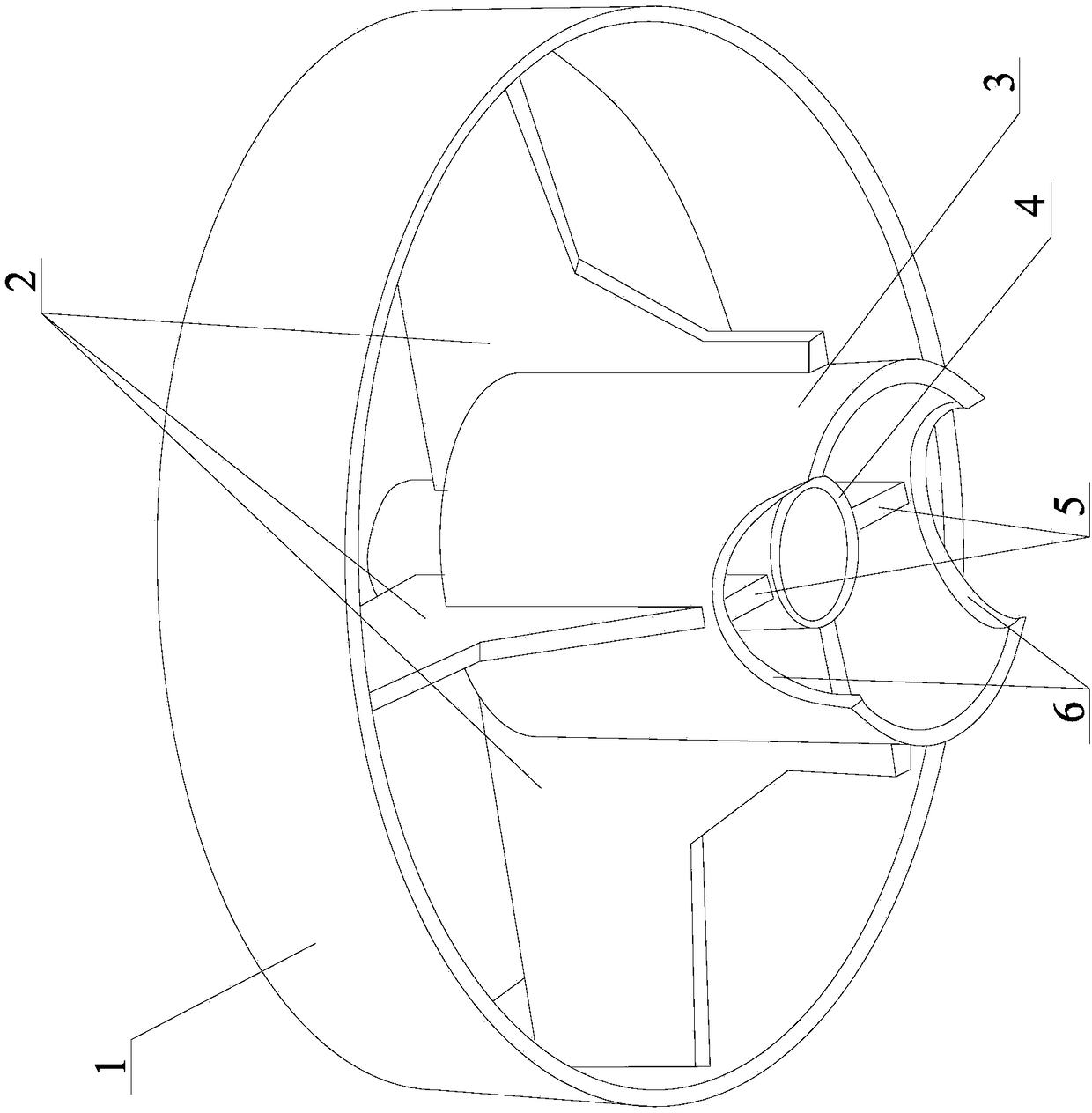
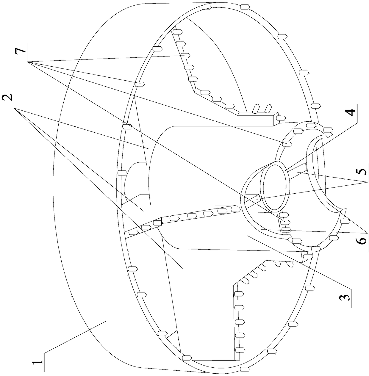
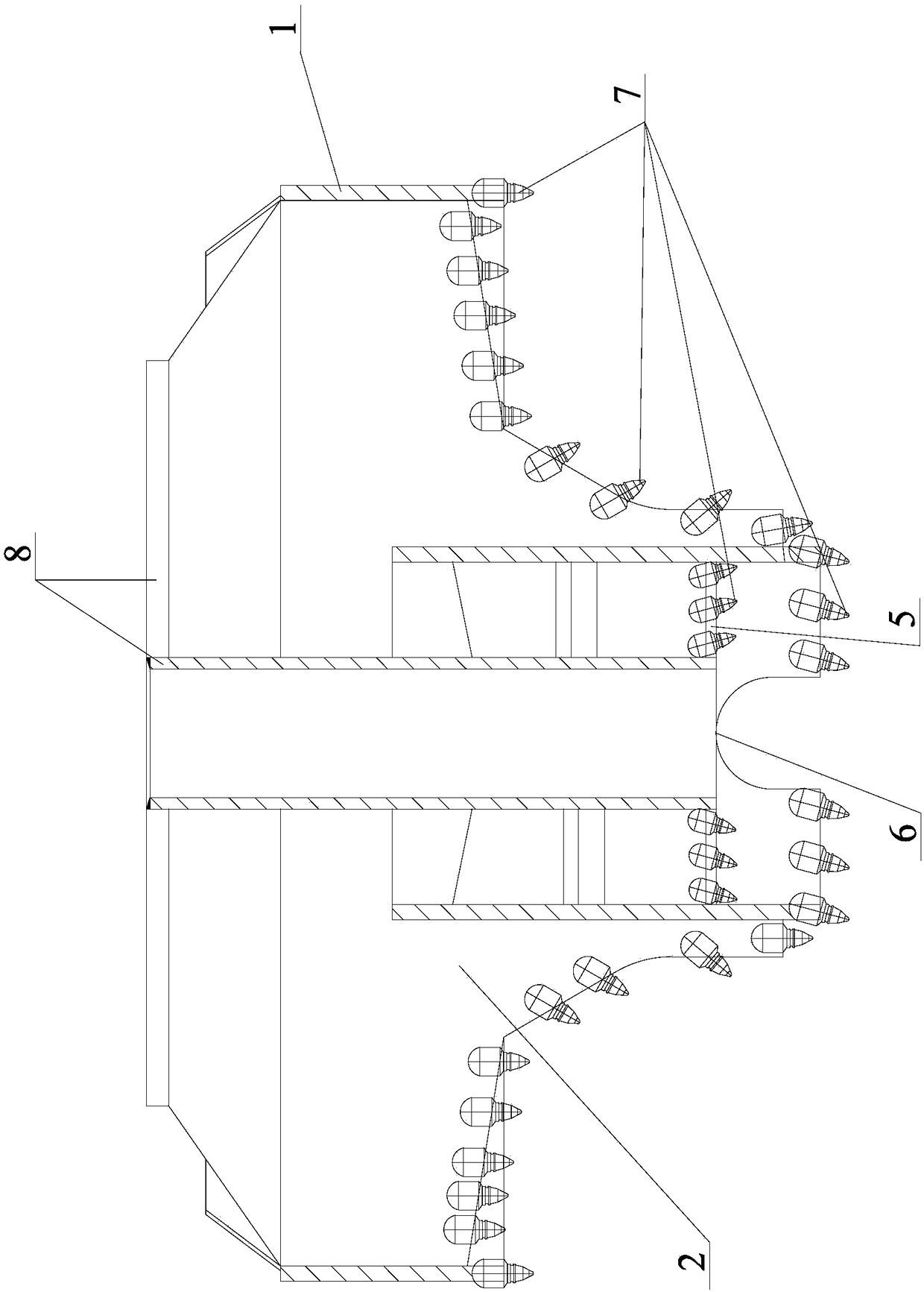
[0019] Such as figure 1 , figure 2 , image 3 , Figure 4 shown

[0020] The drill bit used for the construction of bored piles of the present invention includes a hollow foundation rod 4, and the top of the hollow foundation rod 4 is provided with a connecting portion 8 such as a flange for connecting with a drill pipe of a drilling rig.

[0021] There is a concentric guide drill sleeve 3 on the outside of the hollow base rod 4 , and the outer diameter of the guide d...


PUM


Abstract

The invention discloses a drill bit for construction of a cast-in-situ bored pile. The drill bit comprises a hollow foundation rod, a connecting part positioned at the top end of the hollow foundationrod and used for being connected with a drill stem of a drilling machine, a retainer ring concentric with the hollow foundation rod, a plurality of connecting plates used for being connected with theretainer ring and a plurality of first scraper plates used for being connected with the retainer ring and provided with cutting teeth. A concentric guide drill sleeve is arranged outside the hollow foundation rod; the bottom end face of the guide drill sleeve is arranged to be a plane and the multiple cutting teeth are arranged on the bottom end face in the circumferential direction; the guide drill sleeve extends to the position below the bottom end face of the hollow foundation rod in the axial direction; a plurality of second scraper plates are arranged between the guide drill sleeve and the hollow foundation rod, wherein a plurality of cutting teeth are arranged at the bottom faces of at least two second scraper plates; all the connecting plates connected with the retainer ring and all the first scraper plates connected with the retainer ring at the same plumb line are arranged to be integrated type connecting plates and first scraper plates; and a plurality of cutting teeth are arranged on the bottom end face of the retainer ring. Drill holes, namely formed holes, of the drill bit in slop rock on the interface between soil and soft rock have good perpendicularity.

Description

technical field [0001] The invention relates to the technical field of pile foundation construction, in particular to a drill bit for constructing bored piles. Background technique [0002] Bored piles have the advantages of high bearing capacity, strong adaptability, pile length up to 100 meters, and can reduce the number of piles. The preferred foundation form for tanks and nuclear power plants. The main construction process of concrete bored piles includes: hole formation, slag removal, reinforcement cage lowering, concrete pouring, and testing. In the above-mentioned main construction process, hole formation is a key link, which directly affects the quality of pile formation. And the hole-forming drill bit of prior art generally adopts following structure: comprise hollow base bar, be located at the taper drill point of hollow base bar lower end, be located at outermost retaining ring, connecting retaining ring and hollow base bar middle and upper multiple A connectin...

Claims


Application Information

Patent Timeline
Patent Type & Authority Applications(China)
IPC IPC(8): E21B10/43E21B7/04
CPCE21B10/43E21B7/04
Inventor 付连红徐新战陈保才周跃阳徐斌罗平麻洪富
Owner 浙江易通特种基础工程股份有限公司
Why Eureka
Try Eureka