
Clamping mechanism for turnover box

A technology of clamping mechanism and turnover box, applied in the direction of load hanging components, transportation and packaging, etc., can solve the problems of multiple spaces, large volume, occupation, etc., and achieve the effect of strong practicability and compact overall structure

Inactive Publication Date: 2018-09-28
SHANDONG LABOR VOCATIONAL & TECHN COLLEGE
View PDF9 Cites 3 Cited by
  • Summary
  • Abstract
  • Description
  • Claims
  • Application Information

AI Technical Summary

Problems solved by technology

[0002] Turnover boxes, also known as logistics boxes, are widely used in machinery, automobiles, home appliances, light industry, electronics and other industries. They are resistant to acids, alkalis, oils, non-toxic and tasteless. They can be used to hold food, etc. They are easy to clean and turn over parts. , Stacked neatly, easy to manage, its reasonable design, excellent quality, suitable for transportation, distribution, storage, circulation processing and other links in factory logistics. In various occasions such as warehouses, production sites, etc., as logistics management is increasingly valued by the majority of enterprises, the turnover box helps to complete the generalization and integrated management of logistics containers, and is a must-have for production and distribution companies to carry out modern logistics management. , and in the process of transportation in the entire logistics system, the clamping mechanism is an indispensable part. Most of the turnover box clamping mechanisms on the market are holding clamping clamping mechanisms, which clamp the outer shell of the container from the outside. On the surface, the cargo box is lifted. This structure only relies on friction to clamp, and there is a certain situation that the cargo box falls off, and most of the clamping clamping mechanisms are large in size and take up too much space. , it is more clumsy in the transportation process

Method used


Image

  • Clamping mechanism for turnover box
  • Clamping mechanism for turnover box
  • Clamping mechanism for turnover box

Examples


Embodiment Construction

[0017] In order to make the technical means, creative features, goals and effects achieved by the present invention easy to understand, the present invention will be further described below in conjunction with specific embodiments.

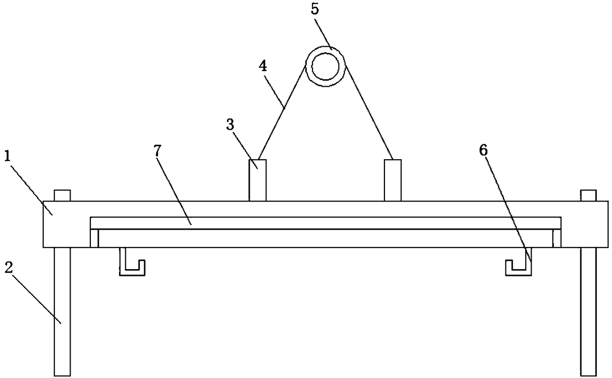
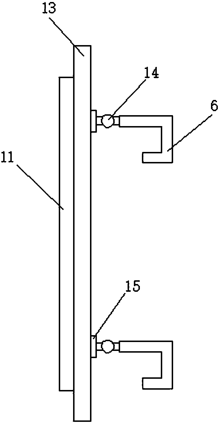
[0018] see Figure 1-3 , the present invention provides a technical solution: a clamping mechanism for a turnover box, its structure includes an iron shell 1, an auxiliary fixing rod 2, a clamping device 7 and a servo electric cylinder 17, the bottom of the iron shell 1 is fixed Connect the auxiliary fixing rod 2, the top of the iron shell 1 is fixedly connected to the iron column 3, the iron column 3 is fixedly connected to the steel wire rope 4, the steel wire rope 4 is fixedly connected to the suspension ring 5, and the inside of the iron shell 1 is provided with a clamp Holding device 7, the bottom of the iron shell 1 is provided with a hook 6, the clamping device 7 includes a fixed frame 16, a servo electric cylinder 17, a transmission rod 18...


PUM


Abstract

The invention discloses a clamping mechanism for a turnover box. The clamping mechanism structurally comprises an iron sheet shell, an auxiliary fixing rod, a clamping device and a servo electric cylinder. The auxiliary fixing rod is fixedly connected with the bottom of the iron sheet shell. An iron column is fixedly connected with the top of the iron sheet shell. A steel wire rope is fixedly connected with the iron column and fixedly connected with a lifting ring. The clamping device is arranged in the iron sheet shell and comprises a fixing frame, the servo electric cylinder, a transmissionrod, a rotary connecting rod and a fixing block. A connecting rod is arranged at the inner bottom of the iron sheet shell. Connecting plates are connected with the upper portion of the connecting rod.A first sliding rail is arranged in the connecting plate. A bearing rod is arranged between the connecting plates. A second sliding rail is arranged at the bottom of the bearing rod. According to theclamping mechanism for the turnover box, through the servo electric cylinder is combined with the rotary connecting rod and matched with the bearing rod and a lifting hook, the turnover box can be safely and stably lifted for transportation.

Description

technical field [0001] The invention relates to the field of logistics storage equipment, in particular to a clamping mechanism for a turnover box. Background technique [0002] Turnover boxes, also known as logistics boxes, are widely used in machinery, automobiles, home appliances, light industry, electronics and other industries. They are resistant to acids, alkalis, oils, non-toxic and tasteless. They can be used to hold food, etc. They are easy to clean and turn over parts. , Stacked neatly, easy to manage, its reasonable design, excellent quality, suitable for transportation, distribution, storage, circulation processing and other links in factory logistics. In various occasions such as warehouses, production sites, etc., as logistics management is increasingly valued by the majority of enterprises, the turnover box helps to complete the generalization and integrated management of logistics containers, and is a must-have for production and distribution companies to car...

Claims


Application Information

Patent Timeline
Patent Type & Authority Applications(China)
IPC IPC(8): B66C1/14B66C1/30
CPCB66C1/14B66C1/30
Inventor 刘大朋赵玉信李东辰杜秀芳江翠翠
Owner SHANDONG LABOR VOCATIONAL & TECHN COLLEGE
Learn More