


Quick Research
Generate reliable direction feasibility study reports for your R&D in just a few steps.

Technical Q&A
Discover and master advanced knowledge NOW. Basics, ideas, possibilities, all at once.

Find Solutions
As an expert in R&D theories, this can generate solutions to your technical problems instantly.

Evaluate Feasibility
Analyze your overall solution with one click, know your potential R&D risks in advance.

Monitor Landscape
Get weekly tech updates, stay abreast of the latest tech innovations and key insights.
Full-automatic thermal shrinkage forming machine
A shrink molding machine, fully automatic technology, applied in the field of automatic heat shrink molding machine, can solve the problems of high risk factor, low efficiency, unsatisfactory heat shrink effect, etc., and achieve the effect of improving heat shrink quality and high efficiency
- Summary
- Abstract
- Description
- Claims
- Application Information
AI Technical Summary
Problems solved by technology
Method used
Image

Examples
no. 1 example
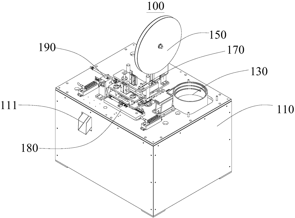
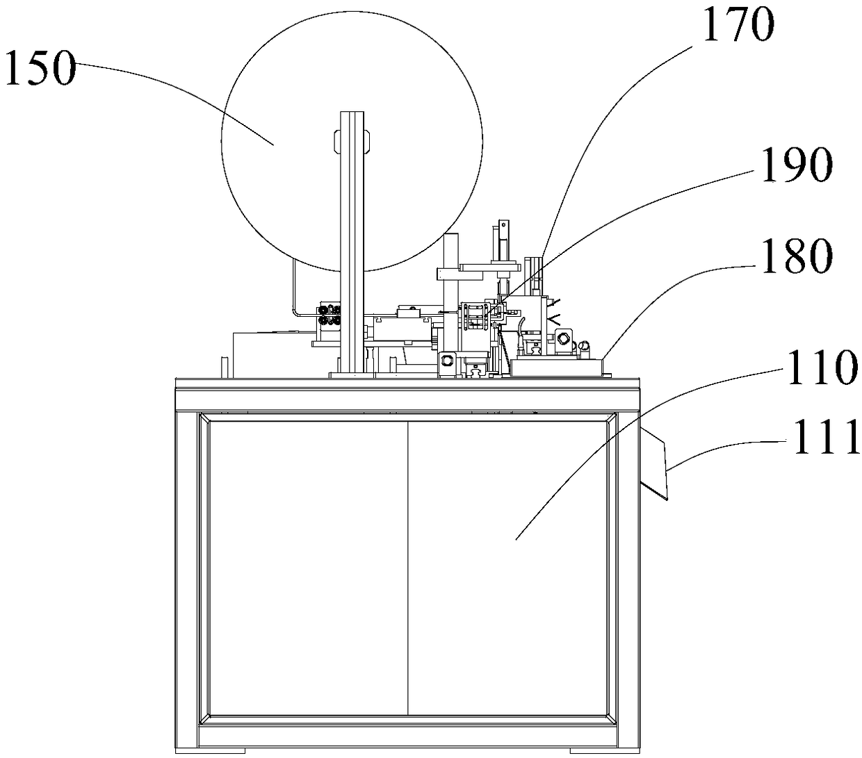
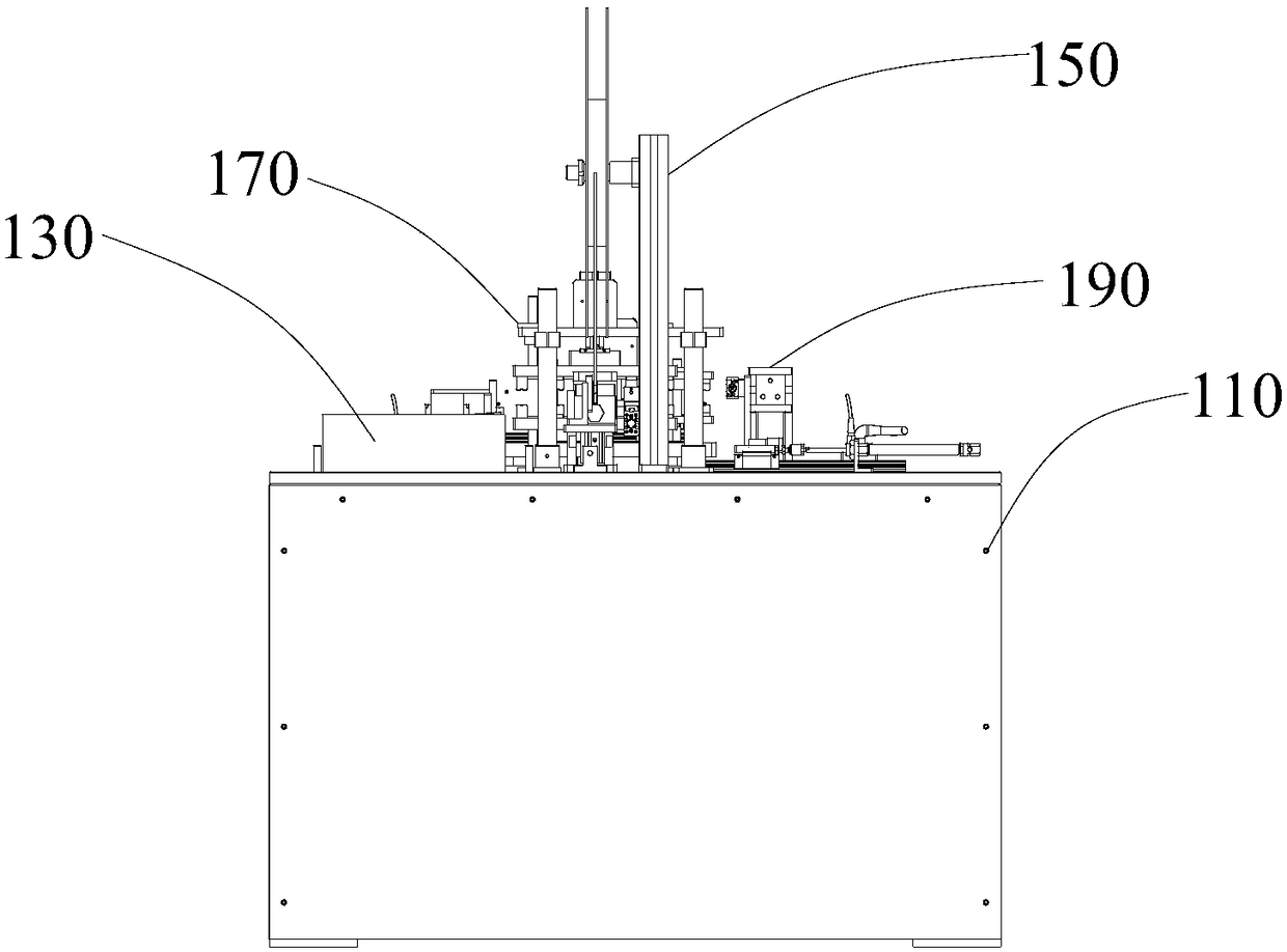
[0035] see in conjunction Figure 1 to Figure 4 , this embodiment provides a fully automatic shrink molding machine 100, including a base 110, a feeding mechanism 130, a tube feeding mechanism 150, a product clamping mechanism 170, a transplanting mechanism 180 and a heat shrinking mechanism 190, on the base 110 There is a storage opening, and the feeding mechanism 130 is set in the storage opening for accommodating and conveying materials. The product clamping mechanism 170, the heat shrinking mechanism 190, the transplanting mechanism 180 and the tube feeding mechanism 150 are all set on the abutment 110 on. The product clamping mechanism 170 is connected with the feeding mechanism 130 and is used for clamping materials. The transplanting mechanism 180 is arranged on one end of the product clamping mechanism 170 and is connected with the transmission of the product clamping mechanism 170 for driving the movement of the product clamping mechanism 170; heat shrink tubing. T...
no. 2 example
[0053] This embodiment provides a fully automatic shrink molding machine 100. Its basic structure, principle and technical effect are the same as those of the first embodiment. Corresponding content in the embodiment.
[0054] The fully automatic shrink molding machine 100 provided in this embodiment includes a power supply device (not shown), a base 110, a feeding mechanism 130, a tube feeding mechanism 150, a product clamping mechanism 170, a transplanting mechanism 180 and a heat shrinking mechanism 190, The abutment 110 is provided with an accommodating opening, and the feeding mechanism 130 is arranged in the accommodating opening for accommodating and conveying materials. Set on the base 110; the product clamping mechanism 170 is connected with the feeding mechanism 130 for clamping materials; the transplanting mechanism 180 is set at one end of the product clamping mechanism 170 and is connected with the product clamping mechanism 170 for driving The product clamping m...
PUM
 Abstract
Description
Claims
Application Information
 - R&D Engineer
- R&D Manager
- IP Professional
- Industry Leading Data Capabilities
- Powerful AI technology
- Patent DNA Extraction
Browse by: Latest US Patents, China's latest patents, Technical Efficacy Thesaurus, Application Domain, Technology Topic, Popular Technical Reports.
© 2024 PatSnap. All rights reserved.Legal|Privacy policy|Modern Slavery Act Transparency Statement|Sitemap|About US| Contact US: help@patsnap.com