
Automatic welding line for LED tube

A technology of LED tube and welding line, applied in welding equipment, laser welding equipment, metal processing equipment, etc., can solve the problems of shortening the service life of LED tube, affecting the appearance of LED tube, and inability to connect with plastic shell, etc. Good effect, high degree of automation, guaranteed appearance effect

Pending Publication Date: 2018-09-28
广东顺德华焯机械科技有限公司
View PDF1 Cites 3 Cited by
  • Summary
  • Abstract
  • Description
  • Claims
  • Application Information

AI Technical Summary

Problems solved by technology

[0002] In the prior art, the connection operation of the plastic shell of the LED lamp tube generally adopts the method of pasting and connecting with glue. This connection method has the following disadvantages: 1. The glue used is a chemical substance with a certain volatility, resulting in a pungent smell , working for a long time will cause the operator to feel uncomfortable, affect their health, and easily suffer from occupational diseases; 2. The glue used is a chemical product, which will pollute the ecological environment when it is improperly operated or leaks; 3. Artificial use of glue for LED When the plastic shell of the lamp tube is connected, the glue is easy to seep out of the surface, which directly affects the appearance of the LED lamp tube; 4. If the glue is applied unevenly, it will directly affect the connection effect and shorten the service life of the LED lamp tube; 5. Use glue The way of connection, after a long time of use, the glue cured product will have physical changes or chemical changes, which will directly affect the connection effect and shorten the service life of the LED tube
This structural welding system can only be applied to the welding of guide wires and power boards, but not to the connection of plastic shells, and the use of laser welding technology to connect plastic shells of LED lamp tubes is still in a blank stage in this industry

Method used


Image

  • Automatic welding line for LED tube
  • Automatic welding line for LED tube
  • Automatic welding line for LED tube

Examples


Embodiment Construction

[0032] The present invention will be further described below in conjunction with the accompanying drawings and embodiments.

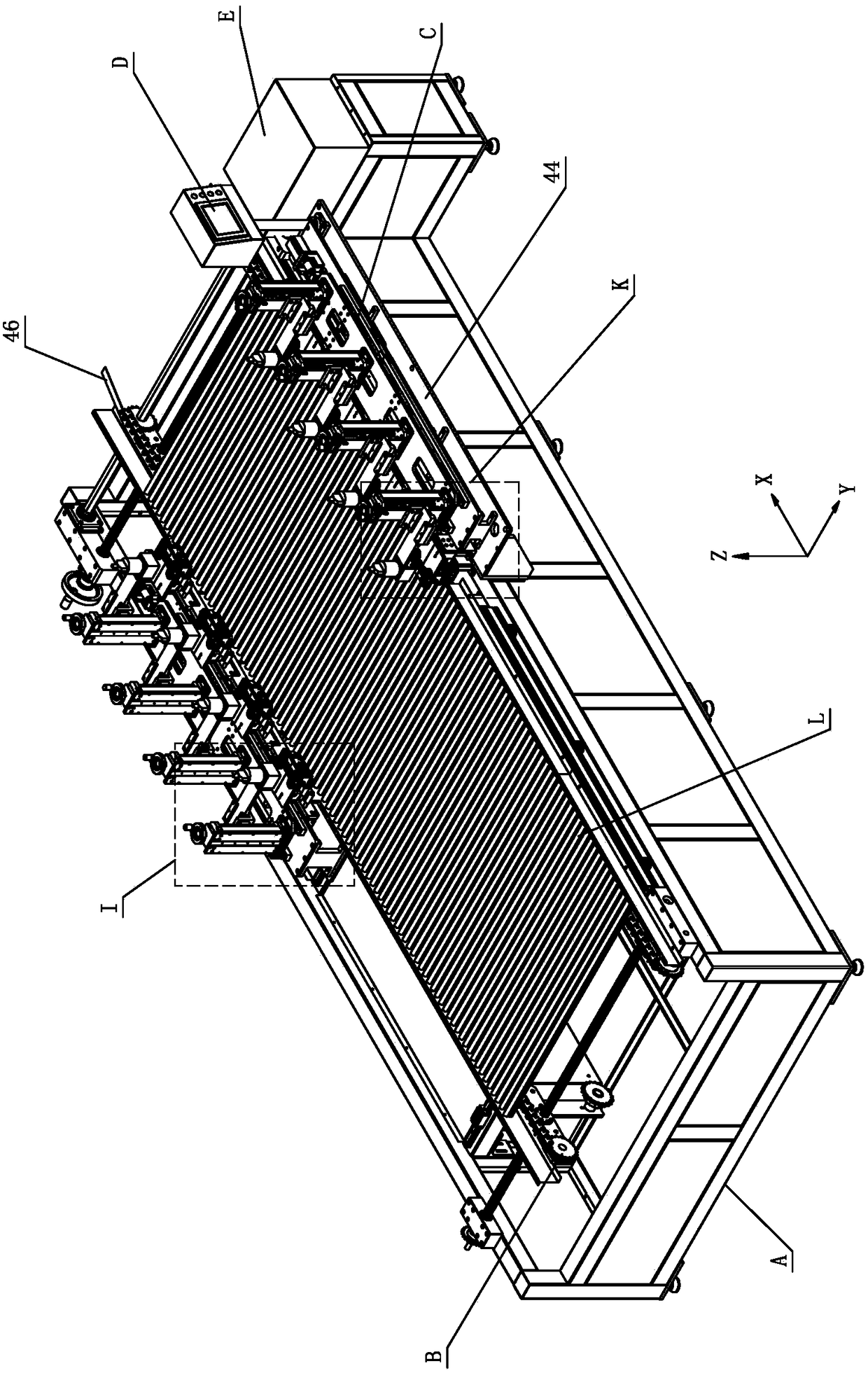
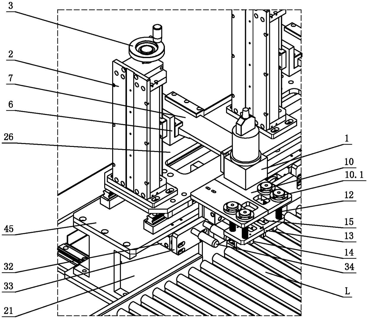
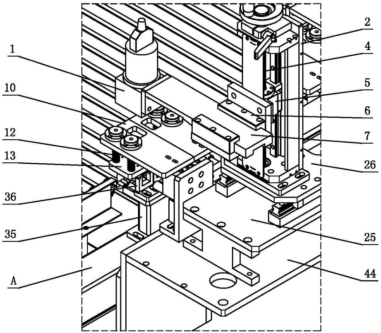
[0033] see Figure 1-Figure 14 , the LED tube automatic welding line, including the tube transmission assembly B and laser welding assembly C installed on the frame A, the tube transmission assembly B is used to transmit several LED tubes L at the same time, laser welding Assembly C is used to weld the first welding position L1 at one end of the LED tube L and the second welding position L2 at the other end (see Figure 13 and Figure 14 ). The starting end of the lamp conveying assembly B is the loading station, the middle of the conveying is the welding station, and the end of the conveying is the unloading station; when working, the worker stands on the side of the lamp conveying assembly B in the feeding station Or both sides of the LED tube L are loaded; the laser welding assembly C is located on the welding station; the end of the frame A is prov...


PUM


Abstract

An automatic welding line for an LED tube comprises a tube transfer assembly and a laser welding assembly; the tube transfer assembly comprises a chain conveyor mechanism and locating transfer blocksarranged on a conveyor chain in the chain conveyor mechanism, and LED tubes are driven to convey by the conveyor chain through the locating transfer blocks; the laser welding assembly comprises laserwelding mechanisms arranged on one side or the both sides of the chain conveyor mechanism; each laser welding mechanism comprises a laser welding component and a welding locating component; the laserwelding component comprises a laser welding joint; the welding locating component comprises transparent pressing blocks and a pressing locating cylinder, and the LED tubes are located and pressed on the locating transfer blocks by the transparent pressing blocks in the pressed state at least; and in work, laser penetrates the transparent pressing blocks for welding the corresponding LED tubes. Theautomatic welding line has the characteristics of reliable performance, high automation degree, low labor cost, and high welding efficiency and welding quality; and connection of plastic cases of theLED tubes through a laser welding technology is pioneered in the industry.

Description

technical field [0001] The invention relates to an automatic welding line, in particular to an automatic welding line for LED lamp tubes. Background technique [0002] In the prior art, the connection operation of the plastic shell of the LED lamp tube generally adopts the method of pasting and connecting with glue. This connection method has the following disadvantages: 1. The glue used is a chemical substance with a certain volatility, resulting in a pungent smell , working for a long time will cause the operator to feel uncomfortable, affect their health, and easily suffer from occupational diseases; 2. The glue used is a chemical product, which will pollute the ecological environment when it is improperly operated or leaks; 3. Artificial use of glue for LED When the plastic shell of the lamp tube is connected, the glue is easy to seep out of the surface, which directly affects the appearance of the LED lamp tube; 4. If the glue is applied unevenly, it will directly affec...

Claims


Application Information

Patent Timeline
IPC IPC(8): B23K26/32B23K26/08
CPCB23K26/0853B23K26/0869B23K26/32
Inventor 丁斌陈伟能梁远威黎家广潘奇才
Owner 广东顺德华焯机械科技有限公司
Learn More