
Treatment system and technology for nitrate production tail gas

A treatment process and treatment system technology, which is applied in the treatment system and treatment process field of nitrate production tail gas, can solve the problems of increased environmental protection risks, increased number of droplets, and increased energy consumption of subsequent treatment sections, so as to improve the activation cycle and improve The effect of the separation effect

Inactive Publication Date: 2018-09-28
襄阳泽东化工集团股份有限公司
View PDF8 Cites 0 Cited by
  • Summary
  • Abstract
  • Description
  • Claims
  • Application Information

AI Technical Summary

Problems solved by technology

[0005] The washing method has the following disadvantages: 1. During the circulation of the washing liquid, the temperature of the mixed gas will be reduced, which increases the energy consumption in the subsequent processing section; 2. When the system pressure changes, it may cause gas carryover in the subsequent processing section. 3. The washing method itself has disadvantages. When the washing liquid is in contact with the mixed gas, the entrainment of liquid droplets in the gas is very serious, and the gas quality in the subsequent sections cannot meet the requirements, resulting in shortened service life of the catalyst. Generally, it takes 2 to 3 months to wash and regenerate the catalyst, which increases the production cost, reduces the stability of the catalytic reaction, and greatly increases the risk of environmental protection.

Method used


Image

  • Treatment system and technology for nitrate production tail gas

Examples


Embodiment 1

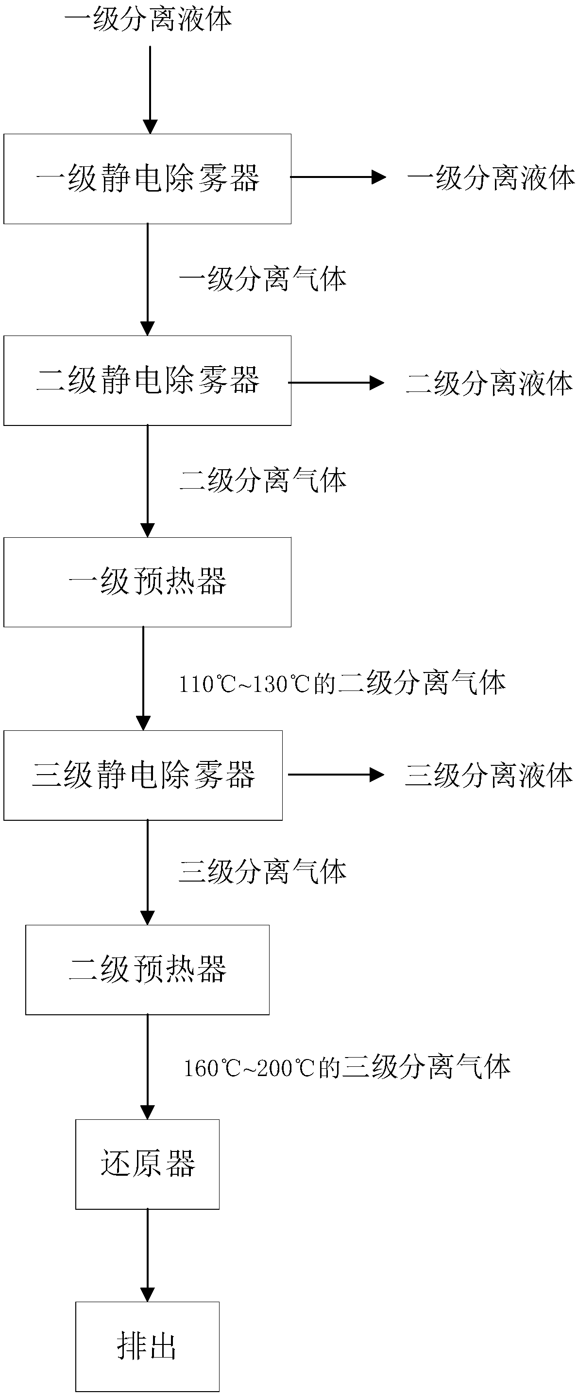
[0036] A treatment system for tail gas from nitrate production, comprising a first-stage electrostatic demister, a second-stage electrostatic demister, a first-stage preheater and a reducer arranged in sequence.

[0037] In this embodiment, a three-stage electrostatic demister is connected between the first-stage preheater and the reducer.

[0038] In this embodiment, a secondary preheater is connected between the three-stage electrostatic demister and the reducer.

Embodiment 2

[0040] Such as figure 1 Shown, a kind of process of processing tail gas of nitrate production comprises the following steps,

[0041] S1: Transport the tail gas from nitrate production at 50°C to a primary electrostatic demister with an operating voltage of 30KV to separate and obtain primary separation liquid and primary separation gas;

[0042] S2: The primary separation gas is separated by a secondary electrostatic demister with an operating voltage of 60KV to obtain a secondary separation liquid and a secondary separation gas;

[0043] S3: The temperature of the secondary separation gas is raised to 110°C and then separated by a three-stage electrostatic demister to obtain a third-stage separation liquid and a third-stage separation gas. The three-stage electrostatic demister is powered by a high-voltage high-frequency power supply. The output voltage of the high-voltage and high-frequency power supply is 110KV, and the output frequency is 200Hz;

[0044] S4: The tempera...

Embodiment 3

[0049] Such as figure 1 Shown, a kind of process of processing tail gas of nitrate production comprises the following steps,

[0050] S1: Transport the nitrate production tail gas at 50°C to the first-stage electrostatic demister with an operating voltage of 50KV to separate and obtain the first-stage separation liquid and the first-stage separation gas;

[0051] S2: The primary separation gas is separated by a secondary electrostatic demister with an operating voltage of 850KV to obtain a secondary separation liquid and a secondary separation gas;

[0052] S3: The temperature of the secondary separation gas is raised to 130°C and separated by a three-stage electrostatic demister to obtain a third-stage separation liquid and a third-stage separation gas. The three-stage electrostatic demister is powered by a high-voltage high-frequency power supply, and the The output voltage of the high-voltage and high-frequency power supply is 120KV, and the output frequency is 300Hz;

[...


PUM


Abstract

The invention belongs to the technical field of tail gas treatment and particularly relates to a treatment system and technology for nitrate production tail gas. The treatment system for the nitrate production tail gas comprises a first-level static demister, a second-level static demister, a first-level preheater and a reducer which are communicated in sequence. Separation is conducted through the multi-level static demisters of different running voltages, the content of impurities in the nitrate production tail gas is gradually lowered, the effect of separating substances such as sodium nitrate and sodium nitrite from moisture and gas is guaranteed, the effect of removing the impurities is stable and reliable, and it is guaranteed that the gas meets the requirements of following workingsegments.

Description

technical field [0001] The invention belongs to the technical field of tail gas treatment, and in particular relates to a treatment system and a treatment process for tail gas from nitrate production. Background technique [0002] The production process of sodium nitrate and sodium nitrite will produce a large amount of tail gas. At present, the ammonia reduction catalytic process is generally used for treatment. Under the action of the catalyst, nitrogen oxides and ammonia undergo catalytic reduction reaction of these tail gases to obtain nitrogen gas, so that the tail gas reaches the national emission standards. [0003] However, in the actual production process, before the nitrate production tail gas enters the catalyst layer, the droplets containing solutes such as sodium nitrate, sodium nitrite and sodium carbonate must be pretreated, otherwise, when the droplets containing the above solutes enter Catalyst layer, after dehydration of the droplets, the outer surface of ...

Claims


Application Information

Patent Timeline
Patent Type & Authority Applications(China)
IPC IPC(8): B01D53/90B01D53/56
CPCB01D53/8621B01D53/90B01D2251/2062B01D2258/02
Inventor 宋开荣陈华胡兵赵杰强
Owner 襄阳泽东化工集团股份有限公司
Learn More