Eureka AIR delivers breakthrough ideas for toughest innovation challenges, trusted by R&D personnel around the world.

Highly-protective chip compensated quartz crystal oscillator

A quartz crystal and protective technology, which is applied in the field of highly protective chip compensation quartz crystal oscillators, can solve problems such as single oscillator structure, short oscillator life, and cumbersome installation process, so as to improve installation accuracy and installation efficiency, Improve structural stability and improve the effect of fixing effect

Pending Publication Date: 2018-09-25
苏州市利明电子有限公司
View PDF0 Cites 0 Cited by
  • Summary
  • Abstract
  • Description
  • Claims
  • Application Information

AI Technical Summary

Problems solved by technology

[0002] In the crystal oscillator, the crystal component that adds an IC inside the package to form an oscillation circuit is called a crystal oscillator. In the actual production process, the crystal oscillator is generally installed manually, and the entire installation process is cumbersome, and in high-intensity In the process of repeated factory work, it is easy to cause precision deviation and affect the quality of the installed oscillator. Moreover, the structure of the oscillator is relatively fixed and single, and it is often installed on the circuit board individually. In actual production, there are still some needs Crystal oscillators installed in an array, and the lack of connectivity between crystal oscillators is not conducive to fast and efficient installation and removal, and the structural stability of the oscillator in the case of maintenance or circuit board exposure to the air Insufficient, easy to be subjected to external force, causing damage, and inexperienced maintenance personnel often try to disassemble the oscillator when performing circuit maintenance, which is easy to cause damage to the internal crystal, and the life of the oscillator that is easy to disassemble and repair is short. , is not conducive to the long-term stable development of the market

Method used


Image

  • Highly-protective chip compensated quartz crystal oscillator
  • Highly-protective chip compensated quartz crystal oscillator
  • Highly-protective chip compensated quartz crystal oscillator

Examples


Embodiment Construction

[0020] The following will clearly and completely describe the technical solutions in the embodiments of the present invention with reference to the accompanying drawings in the embodiments of the present invention. Obviously, the described embodiments are only some, not all, embodiments of the present invention. Based on the embodiments of the present invention, all other embodiments obtained by persons of ordinary skill in the art without making creative efforts belong to the protection scope of the present invention.

[0021] In the description of the present invention, it should be noted that the terms "upper", "lower", "inner", "outer", "front end", "rear end", "both ends", "one end", "another end" The orientation or positional relationship indicated by etc. is based on the orientation or positional relationship shown in the drawings, and is only for the convenience of describing the present invention and simplifying the description, rather than indicating or implying that ...


PUM


Abstract

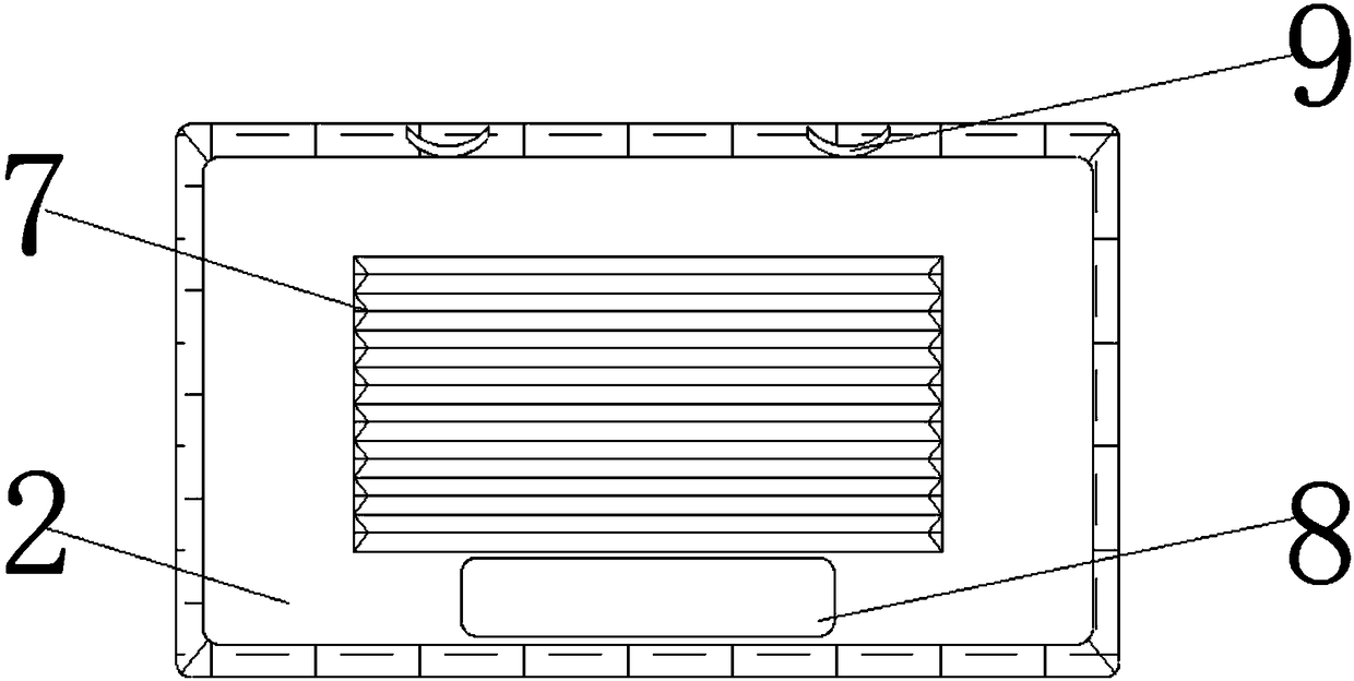
The invention discloses a highly-protective chip compensated quartz crystal oscillator. The highly-protective chip compensated quartz crystal oscillator comprises a mounting substrate, a protective cover and an integrated circuit bare chip, wherein a metal retainer is fixedly arranged at the surface edge of the integrated circuit bare chip; a matching chute is formed in the surface of the protective cover; a reserved slot is formed in a top end of the protective cover; a guide post is mounted on the surface of an inner wall of the protective cover; an oscillator main body is fixedly arranged on the surface of the integrated circuit bare chip on an inner side of the metal retainer; three chip capacitors are mounted on the surface of the integrated circuit bare chip on one side of the oscillator body; a metal block is mounted on the surface of a bottom end of the mounting substrate; and electronic circuit strips are mounted on the surface of a bottom end of the mounting substrate on bothsides of the metal block. Through a series of structures, the oscillator becomes convenient to mount, and has a certain anti-disassembly function. Moreover, the structural stability is enhanced, andsubsequent use is facilitated.

Description

technical field [0001] The invention relates to the technical field of electronic components, in particular to a high-protection chip compensation quartz crystal oscillator. Background technique [0002] In the crystal oscillator, the crystal component that adds an IC inside the package to form an oscillation circuit is called a crystal oscillator. In the actual production process, the crystal oscillator is generally installed manually, and the entire installation process is cumbersome, and in high-intensity In the process of repeated factory work, it is easy to cause precision deviation and affect the quality of the installed oscillator. Moreover, the structure of the oscillator is relatively fixed and single, and it is often installed on the circuit board individually. In actual production, there are still some needs Crystal oscillators installed in an array, and the lack of connectivity between crystal oscillators is not conducive to fast and efficient installation and re...

Claims


Application Information

Patent Timeline
Patent Type & Authority Applications(China)
IPC IPC(8): H03B5/32H03B1/00
CPCH03B1/00H03B5/32
Inventor 周利明
Owner 苏州市利明电子有限公司
Why Eureka
Eureka Blog
Learn More