Beam pumping unit-used direct-drive permanent magnet synchronous motor

A permanent magnet synchronous pumping unit technology, which is applied to synchronous motors, electromechanical devices, electric components, etc. Service life and other issues, to achieve compact layout, improve integrity, and save costs

Pending Publication Date: 2018-09-25
沈阳蓝光驱动技术有限公司
View PDF1 Cites 0 Cited by
  • Summary
  • Abstract
  • Description
  • Claims
  • Application Information

AI Technical Summary

Problems solved by technology

[0004] The purpose of the present invention is to provide a direct-drive permanent magnet synchronous motor for beam pumping units, which solves the problem of poor alignment of installation coaxiality, difficulty in ensuring installation accuracy, and low transmission efficiency when traditional oil pumping units adopt belt transmission. The belt is easy to wear and affect the service life and other problems. The direct connection structure design is reasonable, the layout is compact, the on-site transformation is convenient, the cost is saved, the transmission efficiency is improved, the floor space is reduced, and the adaptability and waterproof requirements of the motor in the open air are improved.

Method used


Image

  • Beam pumping unit-used direct-drive permanent magnet synchronous motor
  • Beam pumping unit-used direct-drive permanent magnet synchronous motor

Examples


Embodiment Construction

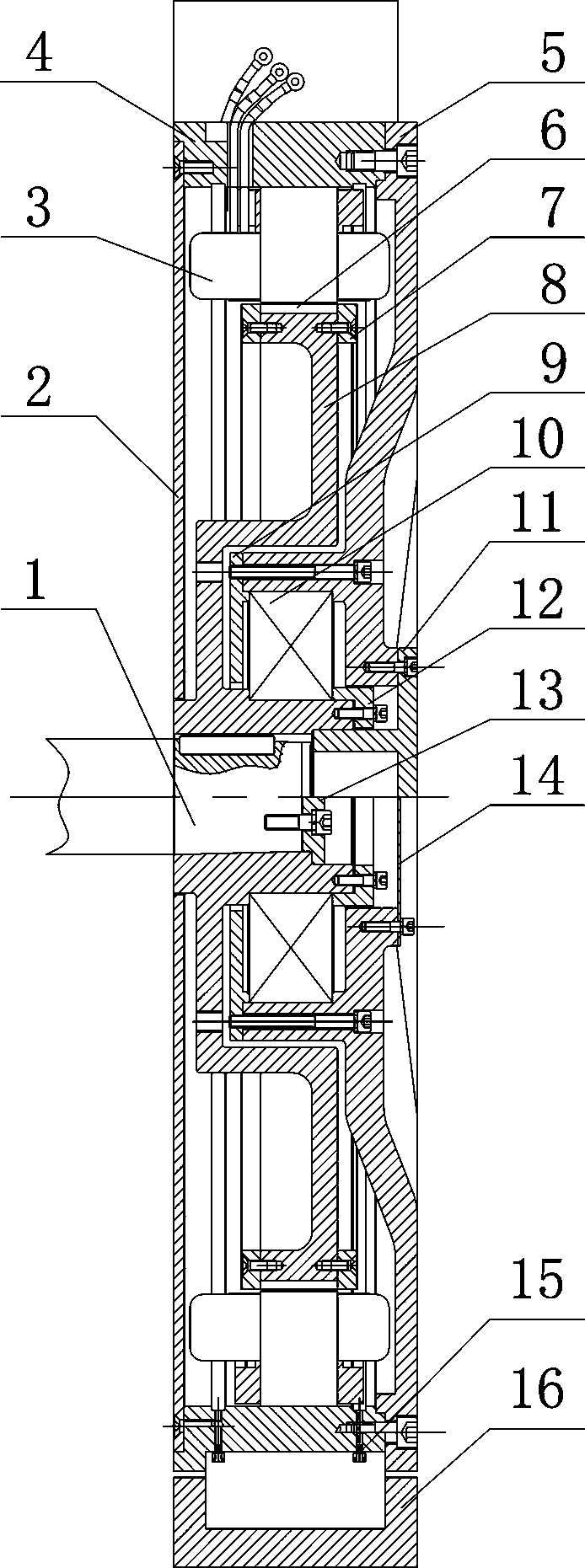
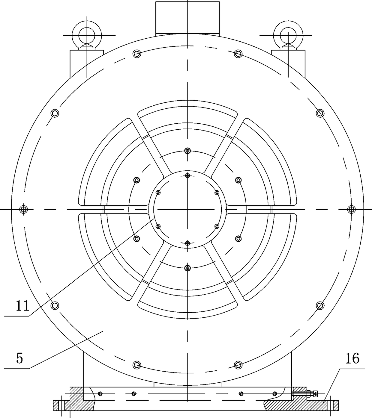
[0015] according to Figure 1~2 The specific structure of the present invention will be described in detail. The direct drive permanent magnet synchronous motor for the beam pumping unit includes a base 16 fixed on the platform of the beam pumping unit, a left end cover 2 and a right end cover 5 assembled on the stator assembly, the stator assembly and the direct reducer The rotor assembly and other components connected to the input shaft 1. The stator assembly is composed of a stator wire package 3 press-fitted in the casing 4. Drainage grooves are arranged on both sides of the stator wire package 3, and a drainage respirator 15 is connected to the bottom of the casing 4 at the drainage groove. The rotor sleeve 8 with the permanent magnet 6 attached to the surface of the rotor assembly is assembled in the shaft hole of the right end cover 5 of the casing 4 through the bearing 10, and the permanent magnet 6 is attached to the rotor sleeve by using the end plates 7 fixed on bo...


PUM


Abstract

The invention discloses a beam pumping unit-used direct-drive permanent magnet synchronous motor, so as to solve the problems that when the traditional beam pumping unit adopts belt drive, the mounting coaxiality centering is poor, the mounting precision is hard to ensure, the drive efficiency is low, and the belt is easy to wear to influence the service life, and the like. The beam pumping unit-used direct-drive permanent magnet synchronous motor comprises a base, and a stator assembly and a rotor assembly assembled on a base. The beam pumping unit-used direct-drive permanent magnet synchronous motor is technically characterized in that a stator coil is pressed in a casing to form the stator assembly; two sides of the stator coil are provided with drain tanks with drain respirators communicated with the bottom part of the casing; a rotor sleeve, with a permanent magnet mounted on the surface, of the rotor assembly is assembled in an axle hole of a right end cover of the casing througha bearing; the input shaft of a reducer inserted in the axle hole of the rotor sleeve is circumferentially limited through a flat key; and a stop cover clamped in an axle hole mouth and fixed at an axle end is used for being axially fixed. The direct connection structure is reasonably designed, the layout is compact, the field reconstruction is convenient, the cost is saved, the drive efficiencyis improved, the occupied area is reduced, and the adaptability and waterproofing requirements of the motor in outdoor work are improved.

Description

technical field [0001] The invention relates to a driving device for oil production equipment in an oil field. In particular, the utility model relates to a direct-drive permanent magnet synchronous motor for a beam pumping unit that can directly drive a reducer without a belt transmission mechanism. Background technique [0002] At present, the beam pumping unit is the dominant oil production equipment in my country's oilfields, and the number of oil wells is large. However, the traditional beam pumping unit driving device consists of three parts: prime mover (mostly asynchronous motor), belt drive, and gearbox. . First of all, because the driving force is not directly transmitted to the beam pumping unit, but is transmitted through a belt transmission mechanism composed of pulleys, belts and many other components, energy loss and a lot of noise will be generated during the transmission of the driving force. This structural characteristic leads to a relatively low overall ...

Claims


Application Information

Patent Timeline
Patent Type & Authority Applications(China)
IPC IPC(8): H02K7/10H02K5/04H02K5/16H02K21/14
CPCH02K7/10H02K5/04H02K5/165H02K21/14
Inventor 梁丙雪王魏徐广人廖国华董胜波黄丽王彭
Owner 沈阳蓝光驱动技术有限公司
Why Eureka
Try Eureka