Head mounted display device and image projection method

A head-mounted display, image technology, applied in the direction of optical components, optics, instruments, etc., to achieve the effect of improving the viewing angle

Active Publication Date: 2018-09-25
HTC CORP
View PDF10 Cites 0 Cited by
  • Summary
  • Abstract
  • Description
  • Claims
  • Application Information

AI Technical Summary

Problems solved by technology

Image device for providing image beam

Method used


Image

  • Head mounted display device and image projection method
  • Head mounted display device and image projection method
  • Head mounted display device and image projection method

Examples


Embodiment Construction

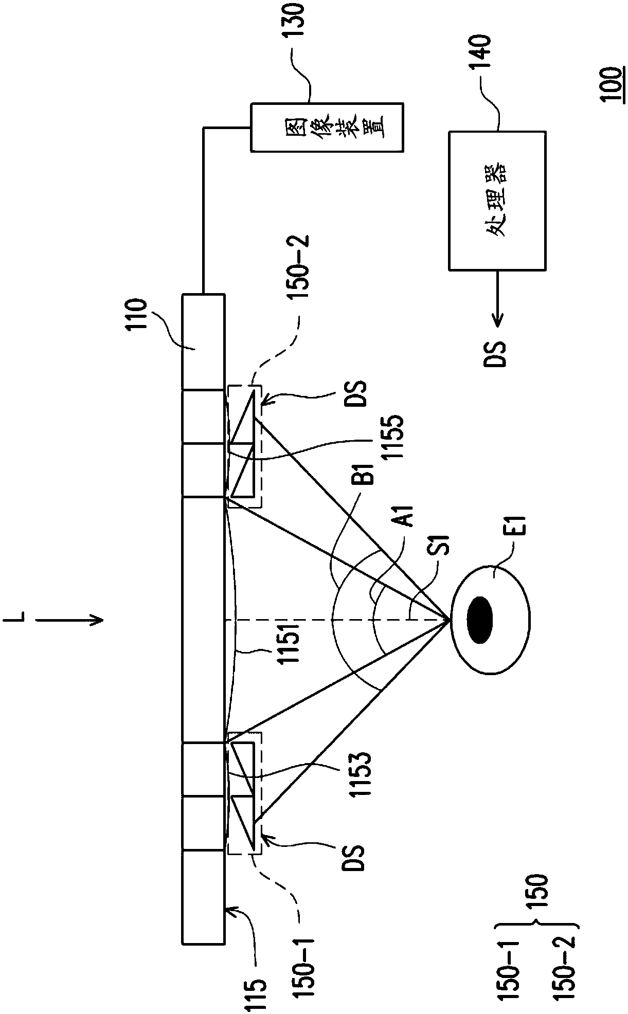
[0049] Please refer to figure 1 , figure 1 A schematic diagram of a head-mounted display device according to an embodiment of the present invention is shown. The head-mounted display device 100 includes an optical waveguide element 110 , an image device 130 and an optical conversion layer 150 . The imaging device 130 is used to provide an image beam (not shown). The optical waveguide element 110 receives the image beam and projects a projected image (not shown) through the surface 115 . The optical conversion layer 150 is configured to overlap the edge of the surface 115, wherein the conversion layer 150-1 is the part of the optical conversion layer 150 located at the edge 1153 of the surface 115, and the conversion layer 150-2 is the part of the optical conversion layer 150 located at the edge of the surface 115 Part 1155. The processor 140 is coupled to the optical conversion layer 150 and generates the command signal DS according to the position of the projection target...


PUM


Abstract

A head mounted display (HMD) device and an image projection method are provided. The head mounted display device includes an optical waveguide device, an image device, an optical conversion layer anda processor. The optical waveguide device receives an image light beam and projects a projection image through a surface. The image device is used to provide the image light beam. The optical conversion layer is disposed overlapping the edge of the surface of the optical waveguide device. The optical conversion layer deflects a portion of the projection image to generate an adjusted projection image according to a command signal, so that the adjusted projection image is transmitted to a projection target. The processor generates the command signal according to a position of the projection target.

Description

technical field [0001] The present invention relates to a display device and an image projection method, and in particular to a head-mounted display device and an image projection method. Background technique [0002] With the rapid development of electronic products, in providing high-quality audio-visual display interface, virtual reality (Virtual Reality, VR) and augmented reality (Augmented Reality, AR) display effects have become the goals pursued by the new generation of display devices. A head mounted display (HMD) is a display device for realizing this technology. [0003] In many known designs of Augmented Reality-Head Mounted Displays (AR-HMD), the viewing angles of the augmented reality images generated by them are too small to allow users to feel realistic and immersive. feeling in it. Therefore, how to make the head-mounted display device have a wider viewing angle has become the focus of attention of those skilled in the art. Contents of the invention [0...

Claims


Application Information

Patent Timeline
Patent Type & Authority Applications(China)
IPC IPC(8): G02B27/01
CPCG02B27/0172
Inventor 萧博文范富诚
Owner HTC CORP
Why Eureka
Try Eureka