
Rotary angle controllable image display system and controlling method thereof

An image display system and image display technology, applied in the field of television

Inactive Publication Date: 2006-11-15
ASUSTEK COMPUTER INC
View PDF0 Cites 8 Cited by
  • Summary
  • Abstract
  • Description
  • Claims
  • Application Information

AI Technical Summary

Problems solved by technology

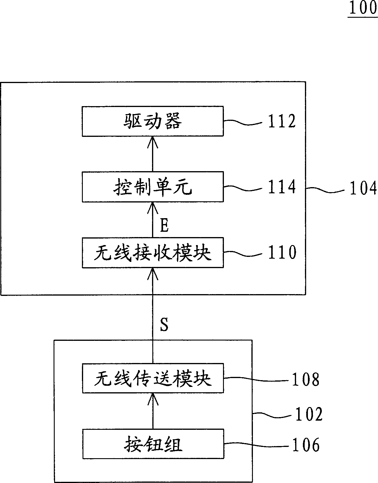
The image display system includes a remote controller and an image display device

Method used


Image

  • Rotary angle controllable image display system and controlling method thereof
  • Rotary angle controllable image display system and controlling method thereof
  • Rotary angle controllable image display system and controlling method thereof

Examples


Embodiment Construction

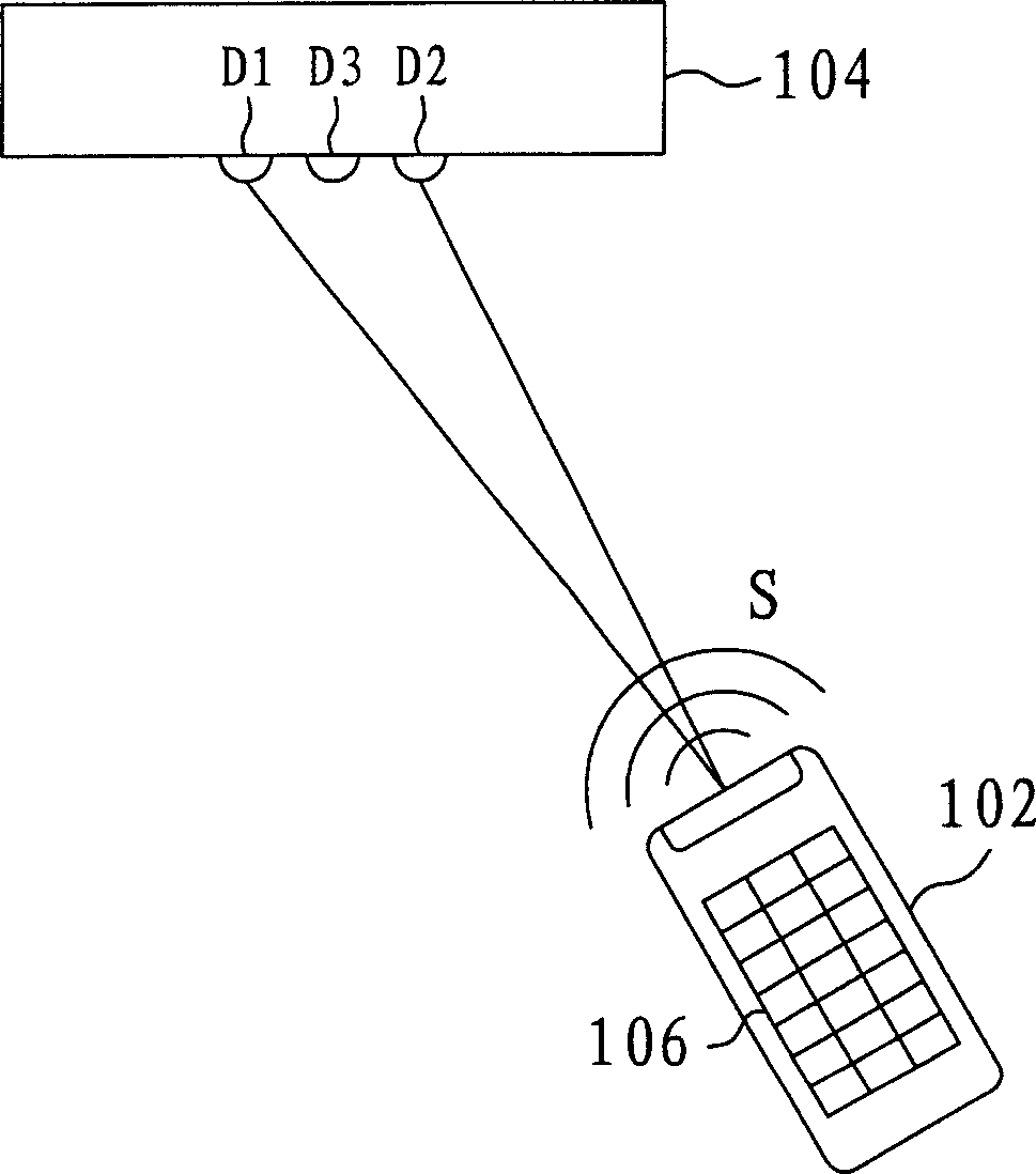
[0011] The invention provides an image display system, such as a television. By detecting the use position of the remote control in the system, the orientation of the display surface of the TV is automatically adjusted to align with the user who is using the remote control, so that the user can obtain a better viewing angle in a simpler way without using The danger and inconvenience of pushing the TV to turn by hand.

[0012] In addition, the TV can be a LCD TV, a plasma TV, or a traditional Cathode Ray Tube (CRT) TV. The image display system of this embodiment can be applied to the above-mentioned TV, and there is no special limitation here. The following is a further description of the present invention with preferred embodiments.

[0013] Please refer to figure 1 , which shows a block diagram of an image display system according to a preferred embodiment of the present invention. The image display system 100 includes a remote controller 102 and an image display device 10...


PUM


Abstract

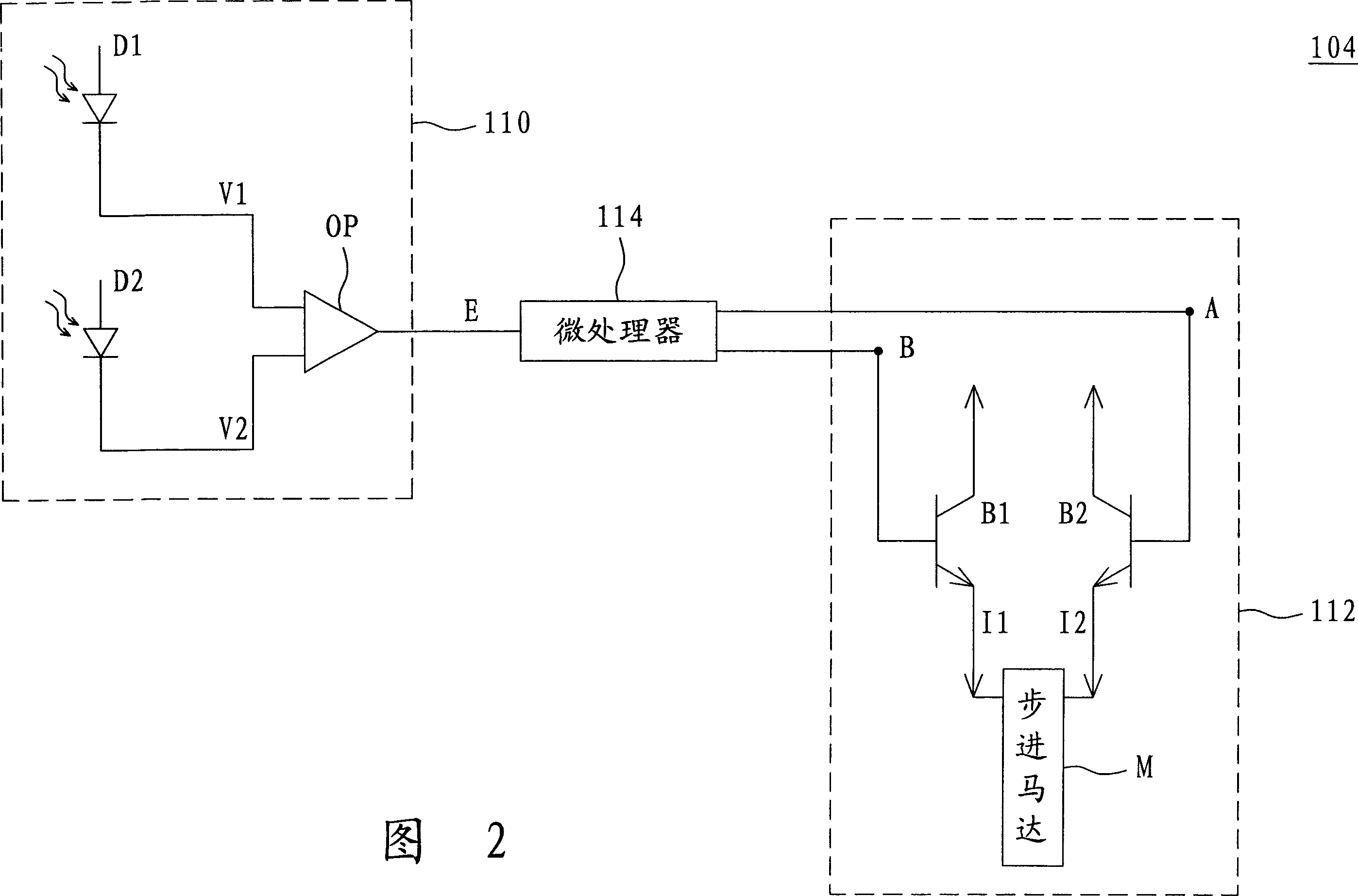
This invention relates to image display system. It includes remote controller and image display device. The controller includes button set and wireless transmission module. The module is used to transform operation signal corresponding to triggered button into wireless signal and output as wireless transmission style when at least one button is triggered. The image display device is used to display image and adjust displaying surface right side up according to the wireless signal. The device includes wireless receive module, drive and control unit. The wireless module receives wireless signal and transforms it into electrical signal for output. The drive is used to drive the displaying device rotating. The control unit is used to control the drive according to the electrical signal to make the displaying device rotate.

Description

【Technical field】 [0001] The present invention relates to an image display system, and in particular to a television with automatic adjustment of viewing angle. 【Background technique】 [0002] Traditional TV sets are mostly placed in a TV cabinet or on a fixed platform at a fixed angle, so the display surface of the TV set also faces a fixed direction. However, the viewing angle of the user in front of the TV is not constant, and the orientation of the display surface of the TV may need to be adjusted due to different sitting positions. Especially for LCD TVs, the viewing angle will affect the viewing image quality. In this situation, the user often needs to push the LCD TV to rotate by hand to obtain a viewing angle with a better picture quality. However, the current LCD TVs are constantly developing toward larger sizes, so the volume and weight of the LCD TVs are increased accordingly. Therefore, it is laborious and dangerous to push the TVs to rotate by hand. For exampl...

Claims


Application Information

Patent Timeline
IPC IPC(8): G12B5/00G05D3/00G09F9/00
CPCF16M11/18F16M11/08
Inventor 钟寿南
Owner ASUSTEK COMPUTER INC
Learn More