
Multifunctional electric automobile charging pile

A technology for electric vehicles and charging piles, applied in electric vehicle charging technology, electric vehicles, charging stations, etc., can solve problems such as single payment method, damage to charging cables, and inconvenience for users, so as to promote market prospects and prevent damage. Effect

Active Publication Date: 2018-09-25
HANGZHOU DIANZI UNIV
View PDF6 Cites 10 Cited by
  • Summary
  • Abstract
  • Description
  • Claims
  • Application Information

AI Technical Summary

Problems solved by technology

[0003] The popular charging piles at this stage only have a single charging function, which does not realize the maximum utilization of resources, and the spare time of car owners during the charging process cannot be fully utilized. Most charging piles pay for charging fees by swiping cards or APPs. Payment methods Relatively simple
[0004] At the same time, most of the existing charging piles directly wrap the charging cable outside the charging device, which is easy to cause damage to the charging cable and poses a great safety hazard
Among them, the patent publication number 201710709094.3 is called a charging pile and charging management system with automatic winding function. It introduces an automatic winding device that uses a motor to drive the winding mechanism. However, this patent is driven by a motor and needs to be pre-set. It is inconvenient for users to set the length of the cable; Patent Publication No. 201710442409.2, named a charging cable retractable device for electric vehicle charging piles, introduces an automatic cable retracting device for charging piles, but the patent During the charging process of the user, the self-locking of the take-up device is not realized

Method used


Image

  • Multifunctional electric automobile charging pile
  • Multifunctional electric automobile charging pile
  • Multifunctional electric automobile charging pile

Examples


Embodiment Construction

[0046] In order to enable those skilled in the art to better understand the technical solutions of the present invention, the multifunctional electric vehicle charging pile of the present invention will be described in detail below in conjunction with the drawings and specific implementation methods.

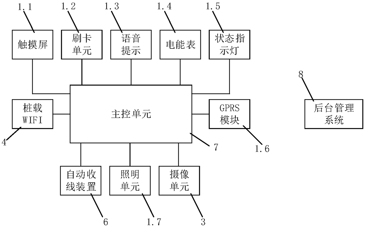
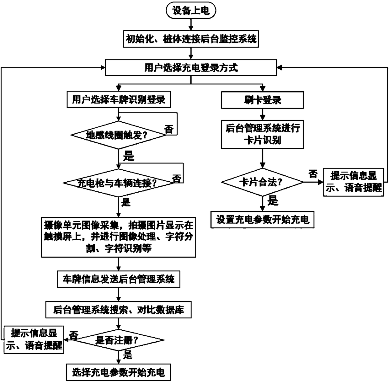
[0047] like figure 1 and 2 As shown, a multifunctional electric vehicle charging pile includes a pile body 1, a charging gun 2 and a base 5, the pile body 1 is installed above the base 5; the charging gun 2 is inserted into the charging gun socket on the side of the pile body 1, and the Connect the charging cable to the charging cable 2.1.

[0048] The front panel of the pile body 1 is provided with a camera unit 3, a touch screen 1.1, a card swiping area 1.2, a voice prompt area 1.3 and a status indicator light 1.5. The pile body 1 is provided with an automatic wire take-up device 6 and a main control unit 7; the automatic wire take-up device 6 can automatically collect and l...


PUM


Abstract

The invention provides a multifunctional electric automobile charging pile, which comprises a pile body, a charging gun and a base, wherein the pile body is mounted above the base; a camera unit, a touch screen, a card swiping region, a voice indication region and a state indication lamp are arranged on a front panel of the pile body; an automatic take-up device and a main control unit are arranged inside the pile body; the camera unit is located at the middle position of the lower part of the front panel; the touch screen is located at the middle position of the upper part of the front panel;the card swiping region and the voice indication region are located on the lower side of the touch screen; the state indication lamp is located on the right side of the touch screen; the automatic take-up device is used for automatically collecting and locking a charging cable; and the main control unit is connected with the components to control the whole charging pile to work. The multifunctional electric automobile charging pile can realize unmanned self-service charging and push merchant information in the spare time of a vehicle owner, and efficiently realize automatic locking and automatic collection of cables by use of a mechanical structure, so that the practicability and the market development potential of the charging pile are greatly improved.

Description

technical field [0001] The invention belongs to the field of electric vehicle charging piles, and in particular relates to a multifunctional electric vehicle charging pile. Background technique [0002] With the rapid development of new energy technology and the increasing number of electric vehicles, AC charging piles, as a kind of electric vehicle charging equipment, are in increasing demand. [0003] The popular charging piles at this stage only have a single charging function, which does not realize the maximum utilization of resources, and the spare time of car owners during the charging process cannot be fully utilized. Most charging piles pay for charging fees by swiping cards or APPs. Payment methods relatively simple. [0004] At the same time, most of the existing charging piles directly wrap the charging cable outside the charging device, which is easy to cause damage to the charging cable and has a great potential safety hazard. Among them, the patent publicati...

Claims


Application Information

Patent Timeline
IPC IPC(8): B60L11/18H04L29/06H04L29/08
CPCH04L63/08H04L67/10B60L53/31H04L67/55Y02T10/70Y02T90/16Y02T90/12Y02T10/7072Y02T90/14
Inventor 许明吴晓萌陈国金
Owner HANGZHOU DIANZI UNIV
Learn More