Overwater-floating photovoltaic power station system adopting rigid horizontal side frame system dragged by inhaul cable in real time

A photovoltaic power station, horizontal edge technology, applied in the direction of photovoltaic power station, photovoltaic power generation, photovoltaic modules, etc., can solve the problems of poor resistance performance, no change or little change in water level, small scale, etc., to expand the construction scope, reduce requirements, The effect of improving safety and reliability

Pending Publication Date: 2018-09-21
THE IT ELECTRONICS ELEVENTH DESIGN & RES INST SCI & TECHNOLOGICAL ENG
View PDF0 Cites 5 Cited by
  • Summary
  • Abstract
  • Description
  • Claims
  • Application Information

AI Technical Summary

Problems solved by technology

[0003] In the past two years, China has gradually started to build floating photovoltaic power stations on water, but the scales are small, and they are all set in still water areas. The water level does not change or changes little. There is no frame structure support, the resistance performance is poor under strong wind and waves, and it cannot adapt to large water level changes

Method used


Image

  • Overwater-floating photovoltaic power station system adopting rigid horizontal side frame system dragged by inhaul cable in real time
  • Overwater-floating photovoltaic power station system adopting rigid horizontal side frame system dragged by inhaul cable in real time
  • Overwater-floating photovoltaic power station system adopting rigid horizontal side frame system dragged by inhaul cable in real time

Examples


Embodiment Construction

[0025] The following will be combined with Figure 1-Figure 5 The present invention is described in detail, and the technical solutions in the embodiments of the present invention are clearly and completely described. Apparently, the described embodiments are only some of the embodiments of the present invention, not all of them. Based on the embodiments of the present invention, all other embodiments obtained by persons of ordinary skill in the art without making creative efforts belong to the protection scope of the present invention.

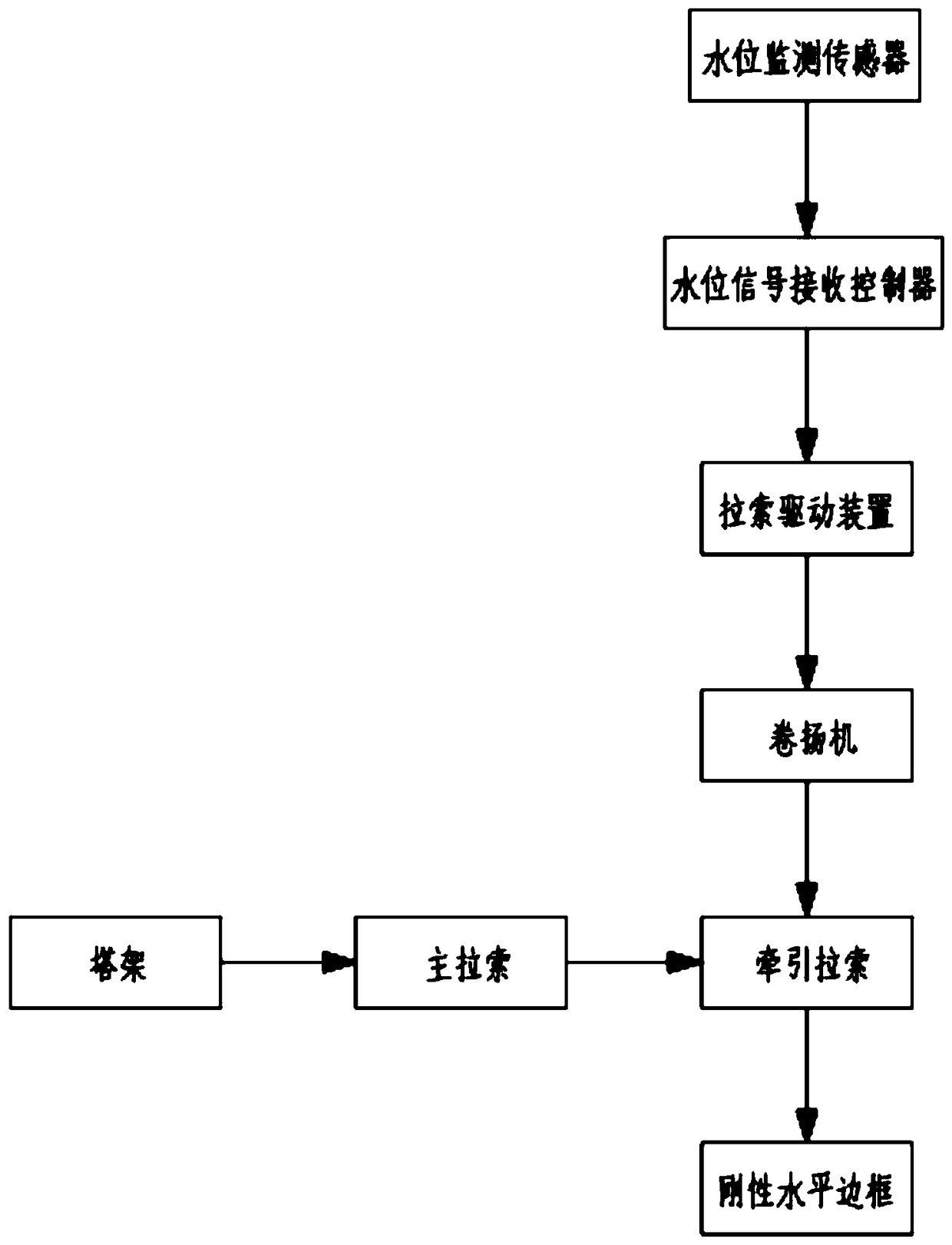
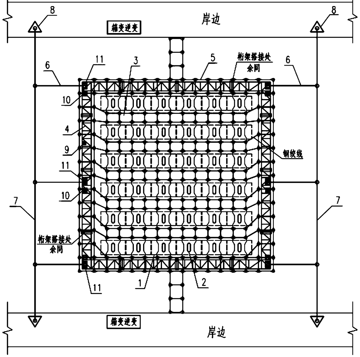
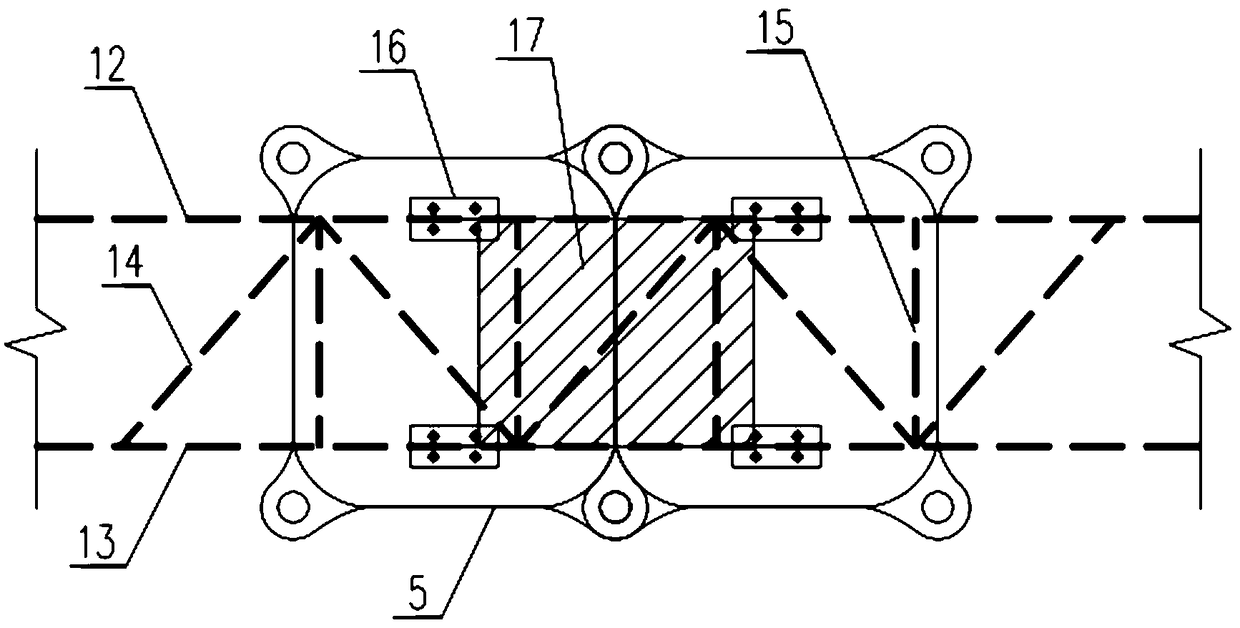
[0026] Through improvement, the present invention provides a floating photovoltaic power station system on water with a rigid horizontal frame system pulled in real time by a cable, which has high wind and wave resistance and is adaptable to large water level changes.

[0027] Such as Figure 1-Figure 5 As shown, it can be implemented in the following manner. Several photovoltaic module strings are respectively laid on several independent fl...


PUM


Abstract

The invention discloses an overwater-floating photovoltaic power station system adopting a rigid horizontal side frame system dragged by an inhaul cable in real time. Improved photovoltaic module strings are paved on floating bodies, and the floating bodies are mutually connected into a whole through floating body connecting bodies and are finally connected with the rigid horizontal side frame system; the rigid horizontal side frame system is dragged and controlled in real time by virtue of a dragging inhaul cable, a real-time water level signal is emitted by a water level monitoring sensor inreal time in the control process and is received by a water level signal receiving controller, and an inhaul cable driving device is controlled to drag the inhaul cable to drag and control the rigidhorizontal side frame system in real time; and a main inhaul cable is tensioned and is arranged on a support tower on a shore. The invention provides a solution method for establishing a photovoltaicpower station on water. The method is applicable to ponds and long-span and water-level-variable water areas such as flowing river surfaces, lake surfaces and reservoirs, and the water areas are adequately utilized, so that the gradually tense problem of lands for ground photovoltaic power stations can be solved.

Description

technical field [0001] The invention relates to the technical field of photovoltaic power stations on water, and specifically relates to a floating photovoltaic power station system on water with a rigid horizontal frame system pulled in real time by a cable. Background technique [0002] In recent years, land resources for the construction of ground-mounted photovoltaic power stations have become increasingly tight, and land resource control has become increasingly stringent. There are 87,873 various types of reservoirs in my country, most of which are only used for irrigation and water storage. The waters of rivers, lakes, seawalls and dams are wider, accounting for about 4% of the inland area, exceeding 170,000 square kilometers, and are widely distributed in electricity consumption. Na area. How to effectively use these waters to build floating photovoltaic power stations on water has become an urgent problem to be solved in the photovoltaic industry. [0003] In the ...

Claims


Application Information

Patent Timeline
Patent Type & Authority Applications(China)
IPC IPC(8): H02S10/00H02S20/00B63B35/44
CPCB63B35/44B63B2035/4453H02S10/00H02S20/00Y02E10/50
Inventor 梁定益陶源
Owner THE IT ELECTRONICS ELEVENTH DESIGN & RES INST SCI & TECHNOLOGICAL ENG
Why Eureka
Try Eureka