
Rotor structural robustness design method for widening built-in permanent magnet synchronous motor speed range

A permanent magnet synchronous motor, rotor structure technology, applied in the magnetic circuit shape/style/structure, magnetic circuit rotating parts, magnetic circuit and other directions, can solve the problem that the permanent magnet magnetic field is difficult to decay, the motor load capacity is weakened, and the motor output is reduced. Small problems such as reducing pulsation and cogging torque, expanding the range of constant power speed regulation, and improving the speed range

Active Publication Date: 2018-09-21
TIANJIN UNIV
View PDF2 Cites 7 Cited by
  • Summary
  • Abstract
  • Description
  • Claims
  • Application Information

AI Technical Summary

Problems solved by technology

[0004] Since most of the magnetic field of the interior permanent magnet synchronous motor is generated by the permanent magnet embedded in the rotor, compared with the electric excitation motor, the permanent magnet magnetic field is difficult to attenuate, which limits the application of the interior permanent magnet synchronous motor to a certain extent. Speed ​​range, when the motor operating environment requires further high-speed operation, the built-in permanent magnet synchronous motor is slightly insufficient
Its maximum speed is related to the permanent magnet flux linkage, d-axis inductance, and phase voltage and phase current limit values. The phase voltage and phase current limit values ​​are fixed values. To obtain a higher speed, it is necessary to reduce the permanent magnet flux linkage or Increasing the d-axis inductance, but reducing the flux linkage of the permanent magnet will reduce the torque of the motor, resulting in a decrease in the output of the motor and weakening the load capacity of the motor. Therefore, a higher speed is usually obtained by increasing the d-axis inductance

Method used


Image

  • Rotor structural robustness design method for widening built-in permanent magnet synchronous motor speed range
  • Rotor structural robustness design method for widening built-in permanent magnet synchronous motor speed range
  • Rotor structural robustness design method for widening built-in permanent magnet synchronous motor speed range

Examples


Embodiment Construction

[0022] Firstly, the robust design method of the rotor structure for widening the rotational speed range of the interior permanent magnet synchronous motor of the present invention will be briefly described below. Include the following steps:

[0023] Step 1: Determine the initial rotor structure of the motor. Among them, the permanent magnet adopts a single-layer "V" structure;

[0024] The second step: Determine the Taguchi method as a method for the robust design of the rotor structure to broaden the speed range of the interior permanent magnet synchronous motor;

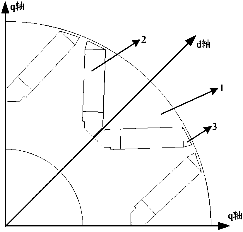
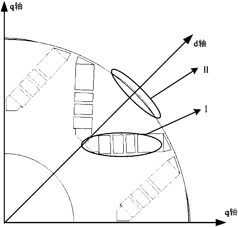
[0025] Step 3: Improve the rotor structure of the motor. First, under the premise of ensuring that the amount of permanent magnets remains unchanged, segment the "V"-shaped permanent magnets. Each part of the permanent magnets is divided into n segments, and the segmented positions are uneven. The d-axis inductance is effectively increased; at the same time, a protrusion in the direction of the air gap is set on...


PUM


Abstract

The invention relates to a rotor structural robustness design method for widening a built-in permanent magnet synchronous motor speed range. The method comprises: determining the initial rotor structure of a motor and providing a permanent magnet with a single-layer V-shaped structure; improving the rotor structure of the motor; using a Taguchi method to optimize the above improved structural scheme, and determining an optimization variable, an optimization objective and a constraint condition; establishing a factor level table; performing finite element simulation on the motor under differentconditions, and obtaining the values of d-axis inductance, the q-axis inductance and the electromagnetic torque under different factor levels; performing average value analysis; performing variance analysis on a result based on the average analysis; and determining the optimal solution and improving a prototype.

Description

technical field [0001] The invention belongs to the field of motor robustness design, and in particular relates to the robustness design of the rotor structure in the rotational speed range of a built-in permanent magnet synchronous motor. Background technique [0002] Permanent magnet synchronous motors are mainly divided into surface mount type, built-in type and claw pole type according to the structure of the rotor magnetic circuit. The built-in permanent magnet synchronous motor is embedded in the rotor core because of the permanent magnet, which causes the asymmetrical and direct axis magnetic circuit ( The direct-axis reluctance is greater than the quadrature-axis reluctance), and the specific performance is that the d-axis inductance is smaller than the q-axis inductance, so it has reluctance torque, which makes it have higher torque density and power density, and compared with the surface mount motor, When the amount of permanent magnets is the same, the d-axis indu...

Claims


Application Information

Patent Timeline
IPC IPC(8): H02K1/27
CPCH02K1/2766
Inventor 夏长亮张杨胜美郭丽艳史婷娜王慧敏
Owner TIANJIN UNIV
Learn More