A Micro Engine Flame Tube with Two-Stage Guide Vanes

A technology of guide vanes and flame tubes, which is applied in the field of micro-engines, can solve the problems of limited improvement of flame surface stability, poor stability, and small range of low-speed areas, and achieve the effects of preventing carbon deposition, uniform mixing, and high turbulence

Active Publication Date: 2020-04-10
NORTHWESTERN POLYTECHNICAL UNIV
View PDF8 Cites 0 Cited by
  • Summary
  • Abstract
  • Description
  • Claims
  • Application Information

AI Technical Summary

Problems solved by technology

However, the range of the low-velocity zone produced by this method is small, the stability is poor, and the stability of the flame surface is limited.

Method used


Image

  • A Micro Engine Flame Tube with Two-Stage Guide Vanes
  • A Micro Engine Flame Tube with Two-Stage Guide Vanes
  • A Micro Engine Flame Tube with Two-Stage Guide Vanes

Examples


Embodiment Construction

[0021] The present invention will be further described now in conjunction with accompanying drawing:

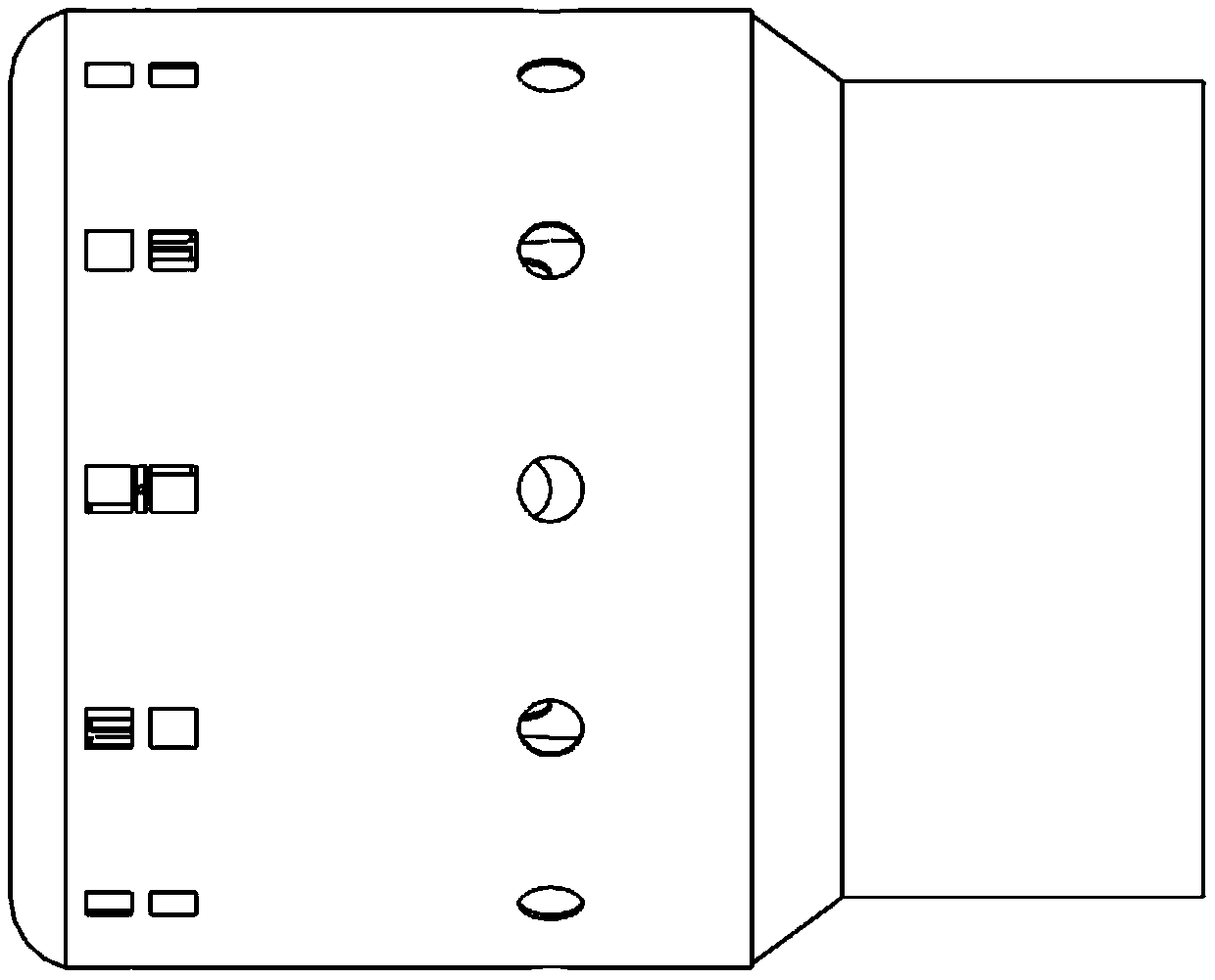
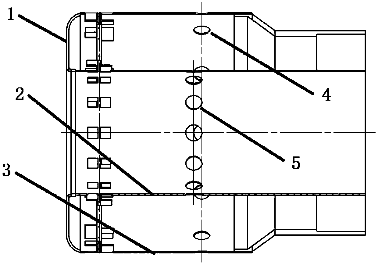
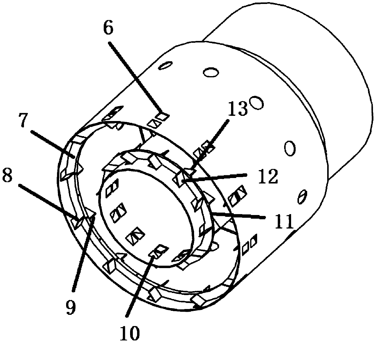
[0022] combine figure 1 , figure 2 , image 3 with Figure 4 , the invention provides a structural design scheme of a micro-engine flame cylinder with two-stage guide vanes. figure 1 is the front view of the flame tube, figure 2 is the sectional view of the flame tube, image 3 In order to remove the three-dimensional schematic diagram of the flame tube on the front face, Figure 4 Sectional view of the split rib.

[0023] according to figure 2 , image 3 with Figure 4 As shown, the present invention rationally designs the main combustion holes of the inner and outer shells of the flame cylinder and sets up two-stage guide vanes, so that the airflow entering the flame cylinder becomes a swirling airflow, and the inwardly rotating airflow and the outwardly rotating The air flow meets and opposes inside the flame tube to form a low-velocity zone. Separation ribs ...


PUM


Abstract

The invention provides a structural design scheme of a micro engine flame tube with two-stage flow guiding vanes. The two-stage flow guiding vanes are arranged on the front portions of an inner shelland an outer shell of the flame tube, so that airflow entering the flame tube is converted into rotating airflow and subjected to counteracting deceleration in the flame tube to form a low-speed zone,the airflow dwell time is increased, and flame stability is improved. Separating fins are arranged between the two-stage flow guiding vanes, the airflow is separated so as to form a shearing layer and improve the structural strength of the flame tube. The separating fin on the outer shell is treated to be hollow to serve as an oil collecting tank, and is provided with an oil inlet hole and an oilspraying hole, the weight is reduced, and the fuel supply problem is solved as well.

Description

technical field [0001] The invention belongs to the field of micro-engines, in particular to a micro-engine flame cylinder with two-stage guide blades. Background technique [0002] In recent years, the microturbine engine has become a research hotspot at home and abroad. It has the advantages of small size, light weight, large output energy, and high density. It is one of the most promising power sources. The working principle of the microturbine engine is similar to that of a large aviation turbojet engine, but its size is much smaller than that of a large aviation turbojet engine. In order to achieve the rated power, the speed is also much higher than that of a common engine. In terms of research on centimeter-scale combustion chambers, the United States is in a leading position, while domestic research is relatively small. Although related research work on micro-combustion chambers has been carried out at home and abroad, there are few studies on the flow characteristics...

Claims


Application Information

Patent Timeline
Patent Type & Authority Patents(China)
IPC IPC(8): F23R3/16
CPCF23R3/16
Inventor 张群张鹏王鑫海涵李承钰寇睿宋亚恒
Owner NORTHWESTERN POLYTECHNICAL UNIV
Why Eureka
Try Eureka