


Quick Research
Generate reliable direction feasibility study reports for your R&D in just a few steps.

Technical Q&A
Discover and master advanced knowledge NOW. Basics, ideas, possibilities, all at once.

Find Solutions
As an expert in R&D theories, this can generate solutions to your technical problems instantly.

Evaluate Feasibility
Analyze your overall solution with one click, know your potential R&D risks in advance.

Monitor Landscape
Get weekly tech updates, stay abreast of the latest tech innovations and key insights.
Solar street lamp pole
A technology for solar street lamps and street light poles, applied in energy-saving lighting, circuit devices, battery circuit devices, etc., can solve the problem of not installing solar cooling devices, etc., and achieve the effect of reasonable design height and strong wind and rain resistance
- Summary
- Abstract
- Description
- Claims
- Application Information
AI Technical Summary
Problems solved by technology
Method used
Image

Examples
specific Embodiment 1
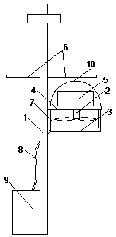
[0026] figure 1 A solar street light pole is shown, including a street light pole body 1, a fan 2 and a water mist device 3, a horizontal support plate 4 is provided in the middle of the street light pole body 1, and a battery 5 is provided on the top of the horizontal support plate 4, and the battery 5 is provided with a solar panel 6, the power output of the solar panel 6 is electrically connected to the power input of the battery 5, the fan 2 is arranged at the bottom of the horizontal support plate 4, the power input of the fan 2 is connected to the power output of the battery 5 Connected, the water mist device 3 includes a water spray pipe and an atomizing nozzle, the water spray pipe is connected to the bottom surface of the horizontal support plate 4 through the connecting rod 7, the height of the water spray pipe is lower than the height of the fan 2, and the atomizing nozzle is arranged on The water spray pipe is close to the side of the fan 2.
[0027] The solar ene...
specific Embodiment 2
[0028] This embodiment further explains the water spray pipe on the basis of the specific embodiment 1. The water spray pipe is an annular pipe, and the projection of the circle center of the area surrounded by the water spray pipe coincides with the projection of the center of the fan 2 .
[0029] The water spray pipe is set in a ring shape, so that the mist water sprayed from the water spray pipe can gather under the fan, so that the wind blown out by the fan can bring more water vapor through the mist water accumulation area, so that the cooling effect can be improved. better.
specific Embodiment 3
[0030] This embodiment further illustrates the water supply structure of the water spray pipe on the basis of specific embodiment 1. The water inlet end of the water spray pipe is connected to the water supply pump in the water supply tank 9 through the water inlet hose 8. The water supply tank 9 is arranged on one side of the bottom of the light pole body 1 .
[0031] The water inlet end of the water supply tank is connected to the municipal pipe network through pipes, and there is a water filling opening on the top of the water supply tank, so that water can be added in two ways, one is through the municipal pipe network, and the other is from the top of the water supply tank. The nozzle is manually filled with water.
PUM
 Abstract
Description
Claims
Application Information
 - R&D Engineer
- R&D Manager
- IP Professional
- Industry Leading Data Capabilities
- Powerful AI technology
- Patent DNA Extraction
Browse by: Latest US Patents, China's latest patents, Technical Efficacy Thesaurus, Application Domain, Technology Topic, Popular Technical Reports.
© 2024 PatSnap. All rights reserved.Legal|Privacy policy|Modern Slavery Act Transparency Statement|Sitemap|About US| Contact US: help@patsnap.com