


Quick Research
Generate reliable direction feasibility study reports for your R&D in just a few steps.

Technical Q&A
Discover and master advanced knowledge NOW. Basics, ideas, possibilities, all at once.

Find Solutions
As an expert in R&D theories, this can generate solutions to your technical problems instantly.

Evaluate Feasibility
Analyze your overall solution with one click, know your potential R&D risks in advance.

Monitor Landscape
Get weekly tech updates, stay abreast of the latest tech innovations and key insights.
Method and device for calculating height of side wall of abrupt slope channel
A calculation method and technology of calculation device, applied in the direction of computer-aided design, calculation, application, etc., can solve the problems of increasing engineering manufacturing cost, large allowance for steep slope channels, waste of building materials, etc., to reduce engineering cost, design highly reasonable, save The effect of production costs
- Summary
- Abstract
- Description
- Claims
- Application Information
AI Technical Summary
Problems solved by technology
Method used
Image

Examples
Embodiment 1
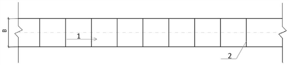
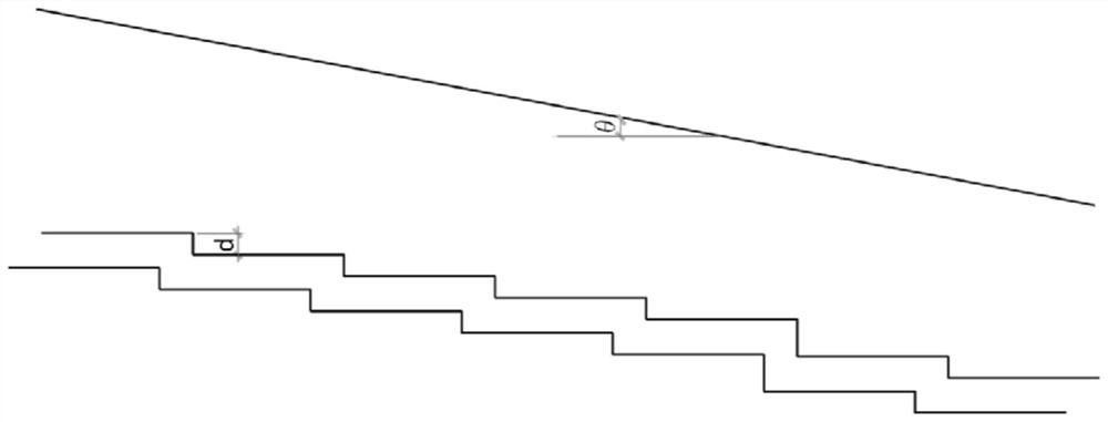
[0063] This embodiment discloses a calculation method for the height of the side wall of a steep slope channel. The side wall of a steep slope channel is as follows: figure 1 and figure 2 As shown, the calculation method includes the following steps:
[0064] Step 1: Calculate the clear water depth h in the steep channel 0 .
[0065] Among them, the calculation of the clear water depth h in the steep slope channel 0 Specifically include:
[0066] Calculate the clear water depth h by the following formula 0 :
[0067] W 0 =(B+mh 0 )h 0 (1)
[0068] In equation (1), W 0 is the water passing area of the section of the steep channel, B is the bottom width of the section of the steep channel, and m is the slope gradient of the section of the steep channel.
[0069] In the present embodiment, the bottom width B of the section of the steep slope channel and the side slope gradient m of the section of the steep slope channel are obtained according to the measurement of ...
Embodiment 2
[0102] This embodiment provides a calculation device for the height of the side wall of a steep slope channel. The calculation device adopts the calculation method for the height of the side wall of the steep channel channel in Embodiment 1 to calculate the height of the side wall. Specifically, it includes a first calculation module, a second A calculation module and a determination module, wherein the first calculation module is used to calculate the clear water depth h in the steep slope channel 0 , the second calculation module is electrically connected to the first calculation module, and is used to calculate the aerated water depth h in the steep slope channel a , the determination module is electrically connected to the first calculation module and the second calculation module respectively, and is used to determine the position of the aeration point and the depth of clear water h 0 and aerated water depth h a Determine the height h of the side wall.
[0103] In this ...
PUM
 Abstract
Description
Claims
Application Information
 - R&D Engineer
- R&D Manager
- IP Professional
- Industry Leading Data Capabilities
- Powerful AI technology
- Patent DNA Extraction
Browse by: Latest US Patents, China's latest patents, Technical Efficacy Thesaurus, Application Domain, Technology Topic, Popular Technical Reports.
© 2024 PatSnap. All rights reserved.Legal|Privacy policy|Modern Slavery Act Transparency Statement|Sitemap|About US| Contact US: help@patsnap.com