High-pressure double-cavity multipurpose water delivery mechanism

A high-pressure, water-inlet chamber technology, applied in the direction of mechanical equipment, machines/engines, liquid fuel engines, etc., can solve the problems of small water pump head, inability to go deep into underwater operations, low efficiency, etc., to achieve large head and save labor time , high efficiency effect

Pending Publication Date: 2018-09-21
KUNMING UNIV OF SCI & TECH
View PDF0 Cites 0 Cited by
  • Summary
  • Abstract
  • Description
  • Claims
  • Application Information

AI Technical Summary

Problems solved by technology

[0004] In order to overcome the deficiencies in the prior art that the pump head is small, the efficiency is low, and it cannot go deep into the water, the present invention provides a high-pressure double-cavity multi-purpose water delivery mechanism different from the technical principle of the original water pump. The water delivery mechanism has a larger head, Higher efficiency and able to work in complex environments

Method used


Image

  • High-pressure double-cavity multipurpose water delivery mechanism
  • High-pressure double-cavity multipurpose water delivery mechanism
  • High-pressure double-cavity multipurpose water delivery mechanism

Examples


Embodiment 1

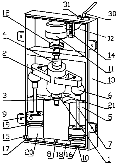
[0032] Embodiment 1: as Figure 1-9 As shown, the high-pressure double-cavity water delivery device includes transmission shaft II1, transmission frame 2, bearing I3, transmission shaft I4, water inlet chamber 5, ball joint 6, piston rod 7, piston 9, water inlet 10, motor 11. Flange coupling 12, box body 13, water outlet 17, water delivery channel 18, water outlet chamber 20; the box body 13 is a hollow sealed box, and the lower part of the box body 13 is provided with a water inlet chamber 5 and a water outlet chamber 20, and the motor 11 is fixed on the inner upper part of the box body 13 by screws 14, the output shaft of the motor 11 is connected with the short shaft 22 on the upper end of the transmission shaft I4 through the flange coupling 12, and the transmission frame 2 includes two outriggers 24 and a base 25, two The outrigger is symmetrically fixed on the upper part of the base, and a through hole 27 is opened at the center of the base. The long shaft 23 at the lowe...

Embodiment 2

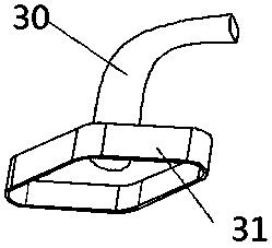
[0033] Embodiment 2: as figure 1 , 8 , 9, and 10, the structure of this embodiment is the same as that of Embodiment 1, the difference is that the piston 9 is provided with a sealing rubber ring 19, and the sealing rubber ring 19 is closely matched with the inner wall of the water inlet chamber 5 or the water outlet chamber 20, and the transmission frame 2, the ball The head universal joint 6 and the piston rod 7 are connected by threads, the box body 13 is provided with a handle, the electric wire 32 connecting the motor and the power supply is arranged in a soft hollow tube 30, and the hollow tube 30 is sealed by a rope cover 31 fixed on the case 13.

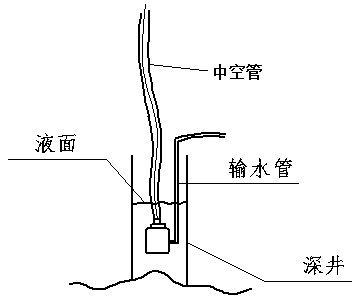
[0034] like Figure 11 , 12 As shown, the device is placed under the water surface of a deep well or reservoir. After the motor 11 is started, the transmission shaft I4 is driven to rotate through the flange coupling 12, and the rotational movement of the transmission shaft I4 and the transmission shaft II1 makes the transm...


PUM


Abstract

The invention discloses a high-pressure double-cavity multipurpose water delivery mechanism and belongs to the field of civil water delivery machinery. The high-pressure double-cavity multipurpose water delivery mechanism is composed of a transmission shaft II, a transmission frame, a bearing I, a transmission shaft I, a water inlet cavity, a ball cardan, a piston rod, a piston, a water inlet, a motor, a flange coupling, a tank, a water outlet, a water delivery channel and a water outlet cavity. The high-pressure double-cavity multipurpose water delivery mechanism achieves water suction and pressurizing according to the principle that reciprocating piston motion can form pressure difference, and meanwhile, by matching with a check valve to control liquid flow direction, achieves high-pressure water delivery in different environments to meet production requirements in real life. The high-pressure double-cavity multipurpose water delivery mechanism is simple in operation and applicable to water delivery in various environments.

Description

technical field [0001] The invention relates to a high-pressure double-cavity multipurpose water delivery mechanism, which belongs to the field of civil water delivery machinery. Background technique [0002] In the northwestern region of our country, due to the low rainfall and the arid geographical environment, most areas in the north are facing severe living conditions of water shortage. In most areas in the north, water wells are used for life and agricultural irrigation. However, in recent years due to The deforestation and the destruction of the ecological environment have caused serious loss of water resources, the weakening of ground water storage capacity, and the continuous increase of the depth of wells, which has brought great difficulties to residents in extracting domestic water. Secondly, in southern China, due to There is a lot of precipitation and there are many lakes, so when the rainy season comes, the water level will often exceed the warning line or even...

Claims


Application Information

Patent Timeline
Patent Type & Authority Applications(China)
IPC IPC(8): F04B47/06F04B17/03F04B23/06F04B53/10F04B49/22
CPCF04B47/06F04B17/03F04B23/06F04B49/22F04B53/10
Inventor 王学军吴鹏伍星普江华伞红军陈明方张鸿许堃
Owner KUNMING UNIV OF SCI & TECH
Why Eureka
Try Eureka