A spatial extension arm driven by telescopic screw
A screw-driven, arm-extending technology, applied in the aerospace field, can solve the problems of limited rocket space and unavailability, and achieve the effect of reducing the retracting height and avoiding interference
- Summary
- Abstract
- Description
- Claims
- Application Information
AI Technical Summary
Problems solved by technology
Method used
Image
Examples
specific Embodiment approach 1
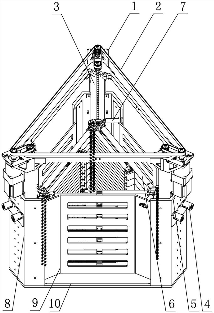
[0033] Specific implementation mode one: combine figure 1 , Figure 10 with Figure 11 Describe this embodiment, a spatial extension arm driven by a telescopic lead screw in this embodiment is characterized in that it includes a synchronous belt drive mechanism 2, an extension arm 6, a fixing plate 8, a connecting plate 9, a base 10, three Stepper motor 1, three telescopic lead screw drive systems 3, three telescopic lead screw in-position locking mechanisms 4, three linear guide rails 5 and three sequential expansion control devices 7, the base 10 is a triangular plate structure, and three fixed plates 8 are evenly distributed on the base 10 along the circumference, and a connecting plate 9 is arranged between two adjacent fixed plates 8 to form a hollow triangular prism-shaped closed structure inside, and three telescopic screw drive systems 3 are evenly distributed on the three sides along the circumference. In the prismatic closed structure, the inner side of each fixed ...
specific Embodiment approach 2
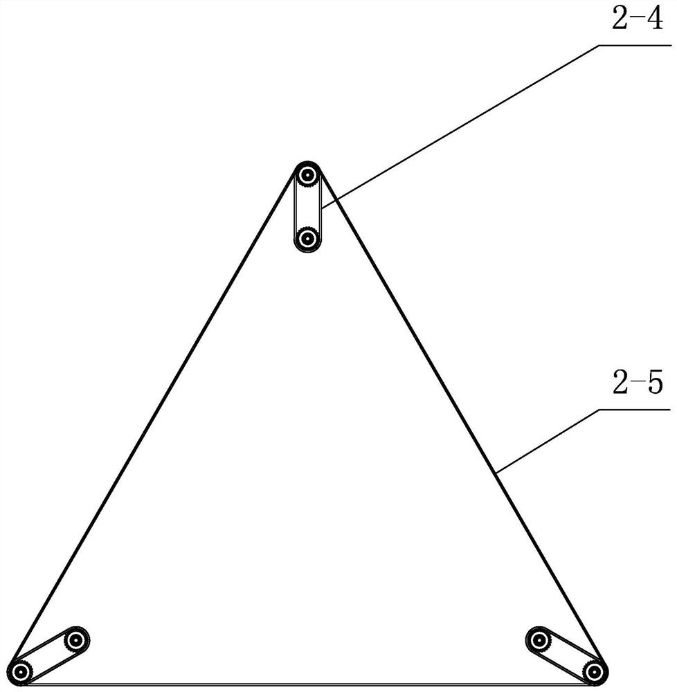
[0035] Specific implementation mode two: combination figure 2 with image 3 Describe this embodiment, the synchronous belt transmission mechanism 2 of this embodiment includes a first synchronous belt transmission unit and three second synchronous belt transmission units, and the three second synchronous belt transmission units are evenly distributed along the circumference on three telescopic screw drives In the upper part of system 3, the first synchronous belt transmission unit is located on the upper part of the three second synchronous belt transmission units. Such setting, on the one hand, the synchronous belt transmission mechanism 2 is used for transmission between the stepper motor 1 and the telescopic screw drive system 3, which avoids interference with the expansion movement of the extension arm 6; on the other hand, three stepper motors 1 drive three A second synchronous belt transmission unit drives the transmission of the first synchronous belt transmission uni...
specific Embodiment approach 3
[0036] Specific implementation mode three: combination Figure 2 to Figure 4Describe this embodiment, each second synchronous belt drive unit of this embodiment comprises the first synchronous pulley 2-1, the 3rd synchronous pulley 2-3 and the first synchronous belt 2-4, the first synchronous pulley 2 -1 is set coaxially with the stepper motor 1, the second synchronous pulley 2-2 is coaxially set with the retractable lead screw in-position locking mechanism 4, between the first synchronous pulley 2-1 and the third synchronous pulley 2-3 Driven by the first synchronous belt 2-4, the first synchronous belt transmission unit includes a second synchronous belt 2-5 and three second synchronous pulleys 2-2, and the second synchronous belt pulley 2-2 is the same as the stepper motor 1 The shaft is set, and the three second synchronous pulleys 2-2 are driven by the second synchronous belt 2-5. So set, the first synchronous belt pulley 2-1, the second synchronous belt pulley 2-2 and t...
PUM
 Abstract
Description
Claims
Application Information
 - R&D Engineer
- R&D Manager
- IP Professional
- Industry Leading Data Capabilities
- Powerful AI technology
- Patent DNA Extraction
Browse by: Latest US Patents, China's latest patents, Technical Efficacy Thesaurus, Application Domain, Technology Topic, Popular Technical Reports.
© 2024 PatSnap. All rights reserved.Legal|Privacy policy|Modern Slavery Act Transparency Statement|Sitemap|About US| Contact US: help@patsnap.com


