Paving equipment for wood plate processing

A technology for wood boards and equipment, applied in the field of paving equipment for wood board processing, can solve the problems of inability to automatically fix a cable disc, poor transmission effect of the reeled wood board, and inability to squeeze the reeled wood board.

Inactive Publication Date: 2018-09-21
王柏彰
View PDF0 Cites 4 Cited by
  • Summary
  • Abstract
  • Description
  • Claims
  • Application Information

AI Technical Summary

Problems solved by technology

[0004] In order to solve the above problems, the present invention provides a paving equipment for processing wood boards, which can solve the problems of high labor intensity, inability to automatically fix the cable discs, and the problems of laying the shaft wood boards on the cable discs. The disk cannot automatically control the rotation, the transmission effect of the disk shaft and wood board is poor, the nailing action of the disk shaft wood board cannot be performed automatically, the disk shaft wood board cannot be squeezed when nailing, the disk shaft wood board is manually pushed, and the disk shaft wood board cannot be positioned Placement, the last piece of shaft plank needs to be manually measured in size, and there is a certain error in the cutting width of the last piece of shaft plank manually; it can realize automatic support and rotation of cable discs of different sizes, and positioning and transmission of the shaft plank to Designate the place, automatically bind the reel plank on the cable disc, with low labor intensity, can automatically fix the cable disc, automatically control the rotation of the cable disc, the transfer effect of the reel plank is good, and automatically align the reel plank Carry out nailing action, squeeze the reel plank when nailing, automatically push the reel plank, position and place the reel plank, automatically measure the size of the last reel plank, and automatically cut the width of the last reel plank accurately Etc

Method used


Image

  • Paving equipment for wood plate processing
  • Paving equipment for wood plate processing
  • Paving equipment for wood plate processing

Examples


Embodiment Construction

[0039] In order to make the technical means, creative features, goals and effects achieved by the present invention easy to understand, the present invention will be further described below in conjunction with specific illustrations. It should be noted that, in the case of no conflict, the embodiments in the present application and the features in the embodiments can be combined with each other.

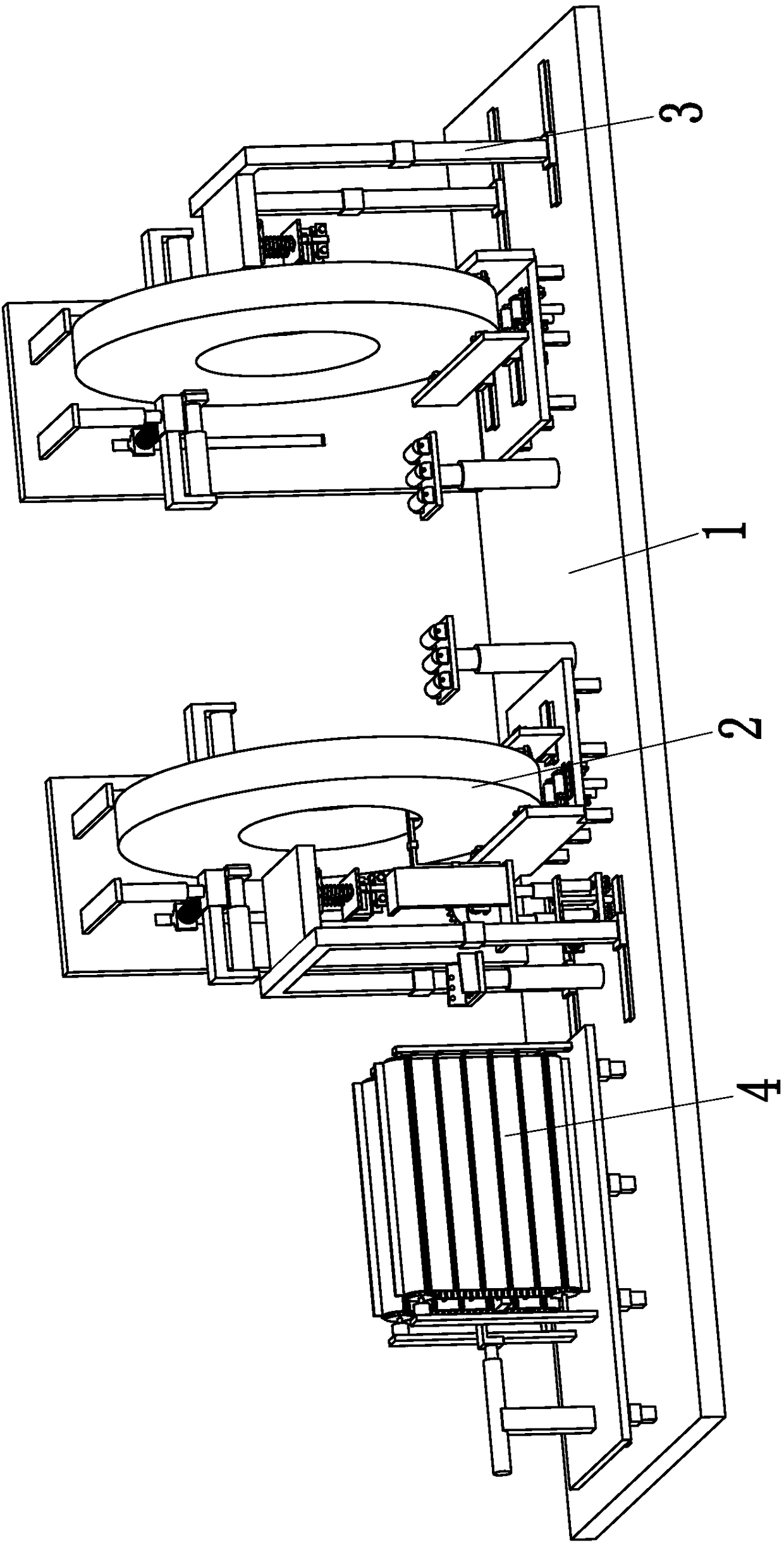
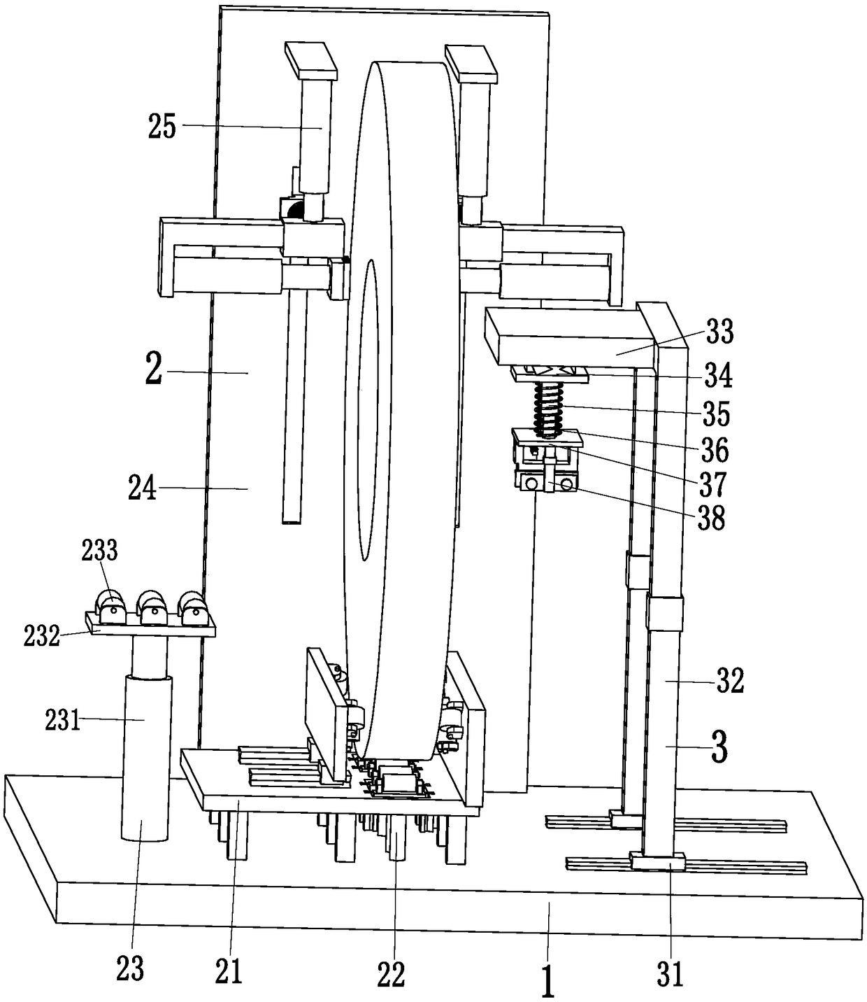
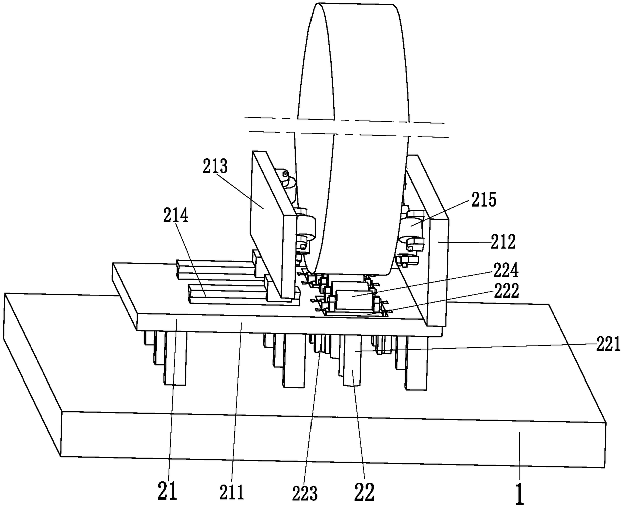
[0040] like Figure 1 to Figure 9 As shown, a kind of paving equipment for wood board processing includes a support base plate 1, two positioning devices 2, a binding device 3 and a discharge device 4, and a chute is arranged on the left end top of the support base plate 1, and the support base plate 1 There are two positioning devices 2 symmetrically installed on the top of each positioning device 2, and a binding device 3 is arranged on the outside of each positioning device 2. side top.

[0041] The positioning device 2 includes a fitting mechanism 21, two sets of supporting mec...


PUM


Abstract

The invention relates to paving equipment for wood plate processing. The paving equipment comprises a supporting bottom plate, two locating devices, binding devices and a discharging device. A slidinggroove is formed in the top of the left end of the supporting bottom plate, and the two locating devices are symmetrically mounted at the top of the supporting bottom plate. The binding devices are arranged on the outer sides of the locating devices correspondingly and mounted at the top of the supporting bottom plate. The discharging device is mounted at the top of the left side of the supporting bottom plate. The problems that when an existing cable disc is paved with a disc shaft wood plate, the cable disc cannot be automatically fixed or automatically controlled to rotate, the disc shaftwood plate cannot be nailed, the disc shaft wood plate cannot be extruded during nailing, the disc shaft wood plate is manually pushed and cannot be located, the size of the last disc shaft wood plateneeds to be manually measured, and the manual cutting width of the last disc shaft wood plate has certain errors can be solved.

Description

technical field [0001] The invention relates to the technical field of wood board processing, in particular to a pavement equipment for wood board processing. Background technique [0002] The cable reel is a reel with the function of winding wires and cables. The large cable reel is basically a wooden reel. Large cables are widely used in oil fields, mines, construction, machinery manufacturing units, scientific research units and many other industries. Factors such as low cost and simple manufacturing process are widely used, and the coil shaft plank is the main structural component in the cable drum. [0003] The production of cable reels is basically carried out manually. First, two hollow cable discs are made, and the two cable discs are fixed. The nail gun nails the reel to the hollow surface of the cable disc, and finally manually rotates the cable disc to complete the nailing of the cable reel. The reel is mainly used to wind up the cable. The problems of this work ...

Claims


Application Information

Patent Timeline
Patent Type & Authority Applications(China)
IPC IPC(8): B27M3/00B27F7/02B27C9/04B27M1/08
CPCB27M3/0073B27C9/04B27F7/02B27M1/08
Inventor 王柏彰
Owner 王柏彰
Why Eureka
Try Eureka