
A switching power supply ripple measurement circuit

A measurement circuit and switching power supply technology, applied in the field of switching power supply ripple measurement circuit, can solve the problems of inconvenience of carrying, low precision, high cost, etc., and achieve the effect of improving safety, eliminating offset error, and reducing measurement error.

Active Publication Date: 2020-11-27
TONGJI UNIV
View PDF8 Cites 0 Cited by
  • Summary
  • Abstract
  • Description
  • Claims
  • Application Information

AI Technical Summary

Problems solved by technology

The above solutions are either inconvenient to carry, or the accuracy is not high, or the cost is high, and they are not widely used in industrial measurement occasions

Method used


Image

  • A switching power supply ripple measurement circuit
  • A switching power supply ripple measurement circuit
  • A switching power supply ripple measurement circuit

Examples


Embodiment

[0074] In this embodiment, the peak value measurement circuit and the valley value measurement circuit share a high-pass filter, DAC, reference voltage source and controller, and the controller adopts a single-chip microcomputer chip.

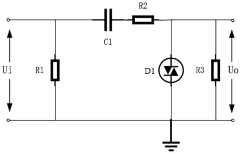
[0075] The high-pass filter of this embodiment is as Figure 6 As shown, C1, C2, R4, and R5 form a second-order high-pass filter, and appropriate parameters need to be selected so that the high-frequency components of the input signal can pass through the filter without attenuation. R1 provides a charge discharge path for C1. When the input is disconnected, C1 discharges through R1 and R4. Otherwise, C1 will retain a high voltage. If the user touches the test clip at this time, it may cause an electric shock. D1 is a bidirectional protection diode, mainly considering that when the tester just contacts the power supply under test, since the voltage across C1 and C2 is zero at this time, if there is no protection diode D1, the high voltage of the...


PUM


Abstract

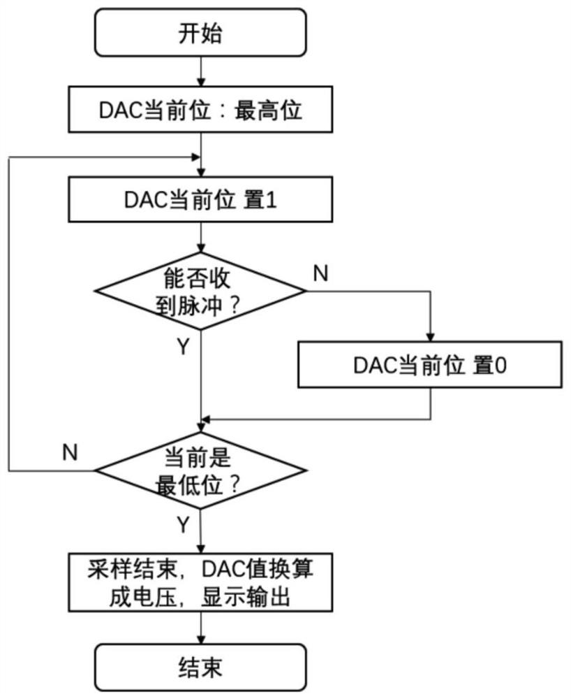
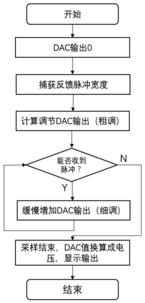
The invention relates to a switching power supply ripple measurement circuit, and the circuit employs a high-speed comparator and a high-precision DAC to realize high-precision ripple measurement under high-frequency conditions. A controller determines the relationship between the output value of the DAC and the peak or valley value of a ripple signal through detecting the presence or absence andwidth of a pulse signal outputted by the high-speed comparator, and adjusts the output of the DAC accordingly. When the controller just cannot detect the pulse signal of the comparator, the peak or valley value of the ripple signal is obtained and a ripple voltage value is obtained through the difference of the peak and valley values. Compared with a scheme that the high-speed ADC is directly employed, the circuit can greatly reduce the measurement cost of ripples, and is lower in measurement errors. Meanwhile, the circuit carries out the peak value measurement and valley value measurement ofthe ripple signal simultaneously, obtains the peak-peak value through the difference of the peak and valley values, and eliminates the offset error of the DAC. A protection circuit is added to a high-pass filter link, thereby improving the safety of a test system.

Description

technical field [0001] The invention relates to the technical field of power supply testing, in particular to a switching power supply ripple measurement circuit. Background technique [0002] Due to the unique chopping mechanism of switching power supply, its output voltage has ripple. Ripple voltage will have an impact on circuits such as operational amplifiers, filters, and A / D conversion. For example, ripples will generate unwanted harmonics in equipment, reducing the efficiency of power supplies; generating surge voltage or current, and burning electrical equipment ; Interfering with the logical relationship of the digital circuit, affecting its normal operation; causing noise interference, making the image and audio equipment unable to work normally. When designing electronic products such as control equipment, electronic instruments, and cameras, the ripple should be minimized. Therefore, accurate measurement of power supply ripple is an important prerequisite for s...

Claims


Application Information

Patent Timeline
Patent Type & Authority Patents(China)
IPC IPC(8): G01R31/40
CPCG01R31/40
Inventor 岳继光刘金承王栗
Owner TONGJI UNIV
Learn More