anti-blocking auger

An auger and helical blade technology, applied in the field of anti-clogging auger, can solve problems such as affecting the drilling progress and easily blocking clay, and achieve the effects of being beneficial to the drilling progress, reducing the weight and having a simple structure

Active Publication Date: 2020-06-02
温州陆华科技有限公司
View PDF7 Cites 0 Cited by
  • Summary
  • Abstract
  • Description
  • Claims
  • Application Information

AI Technical Summary

Problems solved by technology

[0002] At present, in the process of traditional drilling, auger drills are generally used for drilling. Under the drive of the motor, the drill bit is used to drill the hole, and then the hole is enlarged under the rotation of the helical piece, and the rotation of the helical piece and the drill bit can be better. It is beneficial to drilling; but during the drilling process, due to the helical rotation of the helical flakes, the soil in the soil layer will stick to the helical flakes. As the drilling deepens, a large amount of clay is easily blocked between the spiral flakes, thus affecting To the progress of drilling, in order to prevent the clay from clogging the auger, it is necessary to design an anti-blocking auger

Method used


Image

  • anti-blocking auger
  • anti-blocking auger
  • anti-blocking auger

Examples


specific Embodiment approach

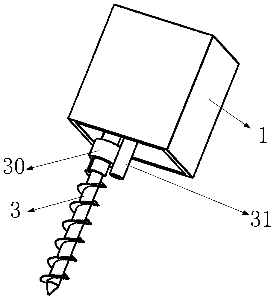
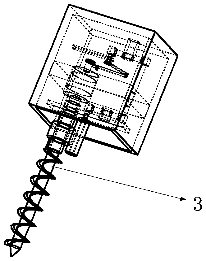
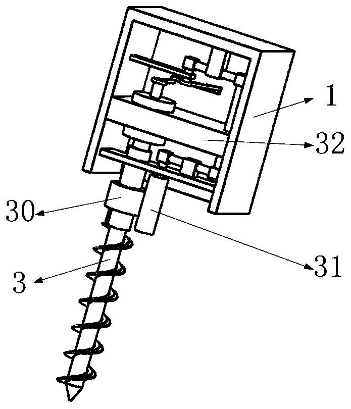
[0050] Specific embodiments: after the motor 2 starts, the motor 2 drives the drill shaft 3 and the drive shaft 38 to rotate through the motor 2 shaft, and the drill shaft 3 drives the first helical piece 19 to rotate, and the drill shaft 3 and the drive shaft 38 always keep rotating at the same speed; According to the working principle of the variable speed double crank mechanism, the drive shaft 38 cannot always keep rotating at the same speed as the first shaft 43, and the speed of the first shaft 43 will be faster than the drive shaft 38 and slower than the drive shaft 38 during the rotation process. situation, then the first shaft 43 passes through a bevel tooth combination, the second shaft 44, the second bevel tooth combination 40, the third shaft 45, the third bevel tooth combination 41, the fourth shaft 46, the fourth bevel tooth combination 42 and the second bevel tooth combination The five-axis 47 drives the drive gear 31 to rotate at a variable speed, and there are ...


PUM


Abstract

The invention belongs to the technical field of twist drills, and particularly relates to an anti-blocking twist drill. The anti-blocking twist drill comprises a driving ring sleeve, a driving gear, afirst fixing plate, a second fixing plate, a third fixing plate, a fourth fixing plate, a fifth fixing plate, a shaft sleeve, a driving shaft, a first cone tooth combination, a second cone tooth combination, a third cone tooth combination, a fourth cone tooth combination and the like. According to the anti-blocking twist drill, repetitive dislocation movement is always kept between a first spiralsheet and a second spiral sheet through a speed-change double-crank mechanism, in this way, clay is difficult to adhere to the first spiral sheet, the situation that the twist drill is blocked by theclay is avoided accordingly, and the drilling depth of the twist drill is greatly benefited. The anti-blocking twist drill is simple in structure and has the good using effect.

Description

technical field [0001] The invention belongs to the technical field of auger drills, in particular to an anti-blocking auger drill. Background technique [0002] At present, in the process of traditional drilling, auger drills are generally used for drilling. Under the drive of the motor, the drill bit is used to drill the hole, and then the hole is enlarged under the rotation of the helical piece, and the rotation of the helical piece and the drill bit can be better. It is beneficial to drilling; but during the drilling process, due to the helical rotation of the helical flakes, the soil in the soil layer will stick to the helical flakes. As the drilling deepens, a large amount of clay is easily blocked between the spiral flakes, thus affecting To the progress of drilling, in order to prevent the clay from clogging the auger, it is necessary to design an anti-blocking auger. [0003] The present invention designs an anti-blocking auger to solve the above problems. Conten...

Claims


Application Information

Patent Timeline
Patent Type & Authority Patents(China)
IPC IPC(8): E21B17/22E21B3/02
CPCE21B3/02E21B17/22
Inventor 不公告发明人
Owner 温州陆华科技有限公司
Why Eureka
Try Eureka