Vertical rod supporting seat movably adjusted on overhung I-shaped steel and construction method of vertical rod supporting seat

A technology of mobile adjustment and I-beam, which is applied to the accessories of scaffolding, house structure support, house structure support, etc., can solve the problems of non-reuse, waste of manpower and material resources, damage to I-beam, etc., and achieve wide practicability and promotion Sexuality, cost saving and work efficiency improvement

Pending Publication Date: 2018-09-18
中建四局建设发展有限公司
View PDF4 Cites 6 Cited by
  • Summary
  • Abstract
  • Description
  • Claims
  • Application Information

AI Technical Summary

Problems solved by technology

This practice may damage the I-beam during the welding process, causing certain safety hazards
When the outer frame is removed, it is necessary to cut the steel bar head, which cannot be reused, resulting in a certain degree of waste
In addition, when the steel bar head is welded, if there is a deviation in positioning and fixing or the frame body needs to be adjusted, it needs to be re-welded, which wastes manpower and material resources

Method used


Image

  • Vertical rod supporting seat movably adjusted on overhung I-shaped steel and construction method of vertical rod supporting seat
  • Vertical rod supporting seat movably adjusted on overhung I-shaped steel and construction method of vertical rod supporting seat
  • Vertical rod supporting seat movably adjusted on overhung I-shaped steel and construction method of vertical rod supporting seat

Examples


Embodiment Construction

[0011] In order to make the purpose, technical solution and advantages of the present invention clearer, the present invention will be further described in detail below in conjunction with the accompanying drawings and embodiments.

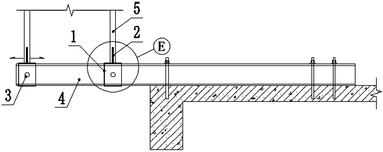
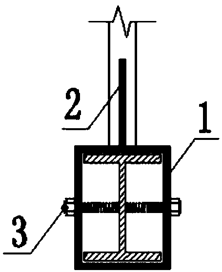
[0012] Embodiment of the present invention: the structural diagram of the movable and adjustable vertical rod support on the cantilevered I-beam is as follows Figure 1~3 As shown, it includes a cantilevered I-beam 4, a square steel sleeve 1 is set on the cantilevered I-beam 4, a connecting rod 2 is welded on the top of the square steel sleeve 1, and a vertical rod 5 is connected on the connecting rod 2. At the same time, both sides of the square steel sleeve 1 are provided with threaded holes, and the bolts 3 are screwed into the threaded holes to contact and tighten with the cantilevered I-beam 4 . Described connecting rod 2 is threaded steel bar, and vertical rod 5 is the steel pipe that the lower end is provided with internal thread, and the l...


PUM


Abstract

The invention discloses a vertical rod supporting seat movably adjusted on overhung I-shaped steel and a construction method of the vertical rod supporting seat. The vertical rod supporting seat comprises the overhung I-shaped steel, the overhung I-shaped steel is sleeved with a square steel sleeve, and a positioning rod is welded to the top of the square steel sleeve. Vertical rods are connectedto the positioning rod, and meanwhile, threaded holes are formed in the two sides of the square steel sleeve. Bolts are screwed into the threaded holes, then make contact with the overhung I-shaped steel and closely abut against the overhung I-shaped steel. According to the vertical rod supporting seat, the square steel sleeve can be movably adjusted on the overhung I-shaped steel, so that the mounting requirements of the vertical rods with the different spacing are met, potential safety hazards due to the fact that a steel bar head is welded to the overhung I-shaped steel through a traditional construction method are avoided, meanwhile, the spacing between the vertical rods and a wall as well as the spacing between the vertical rods can be reasonably adjusted according to the scheme requirements, and the work efficiency is improved; and the dismounted vertical rod supporting seat can be recycled, and the energy saving and environmental protection effects are achieved.

Description

technical field [0001] The invention relates to a movable and adjustable pole support on a cantilevered I-beam, which belongs to the technical field of main structure engineering construction. Background technique [0002] In the field of building construction, the cantilevered outer frame provides an operating platform for construction operations, and at the same time provides edge protection for floors and construction operations, and is widely used. The cantilevered I-beam is an important part of the cantilevered outer frame. The traditional cantilevered I-beam welds two steel bar heads on the top of the I-beam to erect the pole. This practice may damage the I-beam during the welding process, causing certain safety hazards. When the outer frame is removed, it is necessary to cut the steel bar head, which cannot be reused, resulting in a certain degree of waste. In addition, when the steel bar head is welded, if there is a deviation in positioning and fixing or the frame...

Claims


Application Information

Patent Timeline
Patent Type & Authority Applications(China)
IPC IPC(8): E04G5/04E04G3/18
CPCE04G3/18E04G5/046
Inventor 林华湘巫立宁方伟聪陈志伟
Owner 中建四局建设发展有限公司
Why Eureka
Try Eureka