Rod shrinking method for producing optical fiber prefabricated rod
An optical fiber preform and quartz technology, which is used in manufacturing tools, glass manufacturing equipment, etc., can solve the problems of ellipse and unbalanced shrinkage of optical fiber preform, and achieve the advantages of avoiding ellipse shrinkage, improving processing quality and ensuring uniformity. Effect
- Summary
- Abstract
- Description
- Claims
- Application Information
AI Technical Summary
Problems solved by technology
Method used
Image

Examples
Embodiment 1
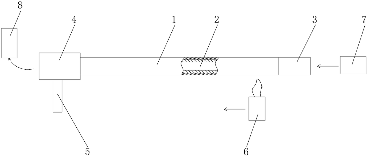
[0027] A. Deposition: high-purity gas SnCl 4 、GeCl 4 , POCl 3 Fluorine etc. and carrier gas O 2 Together, they pass from the gas guide tube 3 into the through hole 2 of the quartz substrate tube 1 rotating around the axis, and the high-temperature hydrogen-oxygen torches are arranged outside the tube of the quartz substrate tube 1 along the axial direction of the quartz substrate tube 1 from one end of the gas guide tube 3 to the rear. One end of the pipeline 4 moves, so that the substance in the tube undergoes an oxidation reaction at high temperature to form a dusty oxide SiO 2 or GeO 2 etc., and deposited on the inner wall of the quartz substrate tube 1, the blowtorch continues to move downstream, and when passing through the loose body that has just been deposited, vitrifies the loose body into a transparent glass body. After the blowtorch reaches the tail of the quartz substrate tube 1, Quickly return to the quartz substrate tube 1 to start the next pass of deposition...
Embodiment 2
[0032] A. Deposition: high-purity gas SnCl 4 、GeCl 4 , POCl 3 Fluorine etc. and carrier gas O 2 Together, they pass from the gas guide tube 3 into the through hole 2 of the quartz substrate tube 1 rotating around the axis, and the high-temperature hydrogen-oxygen torches are arranged outside the tube of the quartz substrate tube 1 along the axial direction of the quartz substrate tube 1 from one end of the gas guide tube 3 to the rear. One end of the pipeline 4 moves, so that the substance in the tube undergoes an oxidation reaction at high temperature to form a dusty oxide SiO 2 or GeO 2 etc., and deposited on the inner wall of the quartz substrate tube 1, the blowtorch continues to move downstream, and when passing through the loose body that has just been deposited, vitrifies the loose body into a transparent glass body. After the blowtorch reaches the tail of the quartz substrate tube 1, Quickly return to the quartz substrate tube 1 to start the next pass of deposition a...
Embodiment 3
[0037] A. Deposition: high-purity gas SnCl 4 、GeCl 4 , POCl 3 Fluorine etc. and carrier gas O 2 Together, they pass from the gas guide tube 3 into the through hole 2 of the quartz substrate tube 1 rotating around the axis, and the high-temperature hydrogen-oxygen torches are arranged outside the tube of the quartz substrate tube 1 along the axial direction of the quartz substrate tube 1 from one end of the gas guide tube 3 to the rear. One end of the pipeline 4 moves, so that the substance in the tube undergoes an oxidation reaction at high temperature to form a dusty oxide SiO 2 or GeO 2 etc., and deposited on the inner wall of the quartz substrate tube 1, the blowtorch continues to move downstream, and when passing through the loose body that has just been deposited, vitrifies the loose body into a transparent glass body. After the blowtorch reaches the tail of the quartz substrate tube 1, Quickly return to the quartz substrate tube 1 to start the next pass of deposition...
PUM
 Abstract
Description
Claims
Application Information
 - R&D
- Intellectual Property
- Life Sciences
- Materials
- Tech Scout
- Unparalleled Data Quality
- Higher Quality Content
- 60% Fewer Hallucinations
Browse by: Latest US Patents, China's latest patents, Technical Efficacy Thesaurus, Application Domain, Technology Topic, Popular Technical Reports.
© 2025 PatSnap. All rights reserved.Legal|Privacy policy|Modern Slavery Act Transparency Statement|Sitemap|About US| Contact US: help@patsnap.com