
Panel cutting device

A cutting device and plate technology, applied in welding equipment, gas flame welding equipment, metal processing equipment, etc., can solve the problems of high cutting efficiency, small equipment investment, low work efficiency, etc., achieve high cutting efficiency, small equipment investment, good cutting effect

Active Publication Date: 2018-09-18
ZHEJIANG JIRUN AUTOMOBILE +2
View PDF10 Cites 2 Cited by
  • Summary
  • Abstract
  • Description
  • Claims
  • Application Information

AI Technical Summary

Problems solved by technology

[0004] The present invention overcomes the shortages of low working efficiency, high labor intensity, incomplete cutting and large investment in equipment of the existing steel plate material cutting device, and provides a plate cutting device which has high working efficiency, low labor intensity and low cutting cost for steel plate material. Completely, there is no phenomenon that the steel plate material is not cut, and the equipment investment is small, especially suitable for cutting batch steel plate materials and thicker steel plate materials, with good cutting effect and high cutting efficiency

Method used


Image

  • Panel cutting device
  • Panel cutting device
  • Panel cutting device

Examples


Embodiment

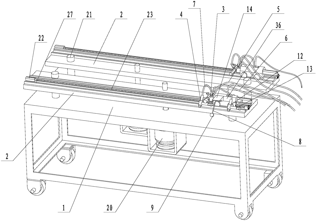
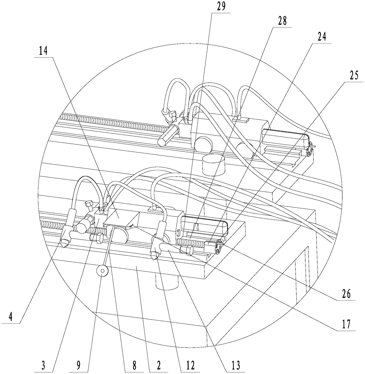
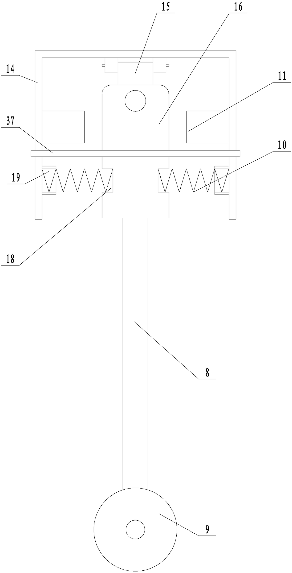
[0024] Embodiment: a kind of plate cutting device (see attached Figures 1 to 4), including a workbench 1, on which a long clamping bar 2 can be lifted and lowered. A clamping drive mechanism for driving the lifting movement of the clamping strips is installed under the workbench. Each clamping strip is correspondingly provided with a clamping drive mechanism. The clamping drive mechanism includes a clamping hydraulic cylinder 20, and the telescopic rod of the clamping hydraulic cylinder is fastened. Connected to the clamping bar, guide columns 21 are provided on the workbench close to the front and rear ends of the clamping bar, and the clamping bar is movably socketed on the guiding column. The clamping bar is connected with a cutting trolley 36 and a driving mechanism that drives the sliding of the cutting trolley. The propelling mechanism includes a driving motor 22 and a screw mandrel 23. The driving motor is installed on the front end of the clamping bar, and one end of ...


PUM


Abstract

The invention discloses a panel cutting device which aims to overcome the deficiency that existing steel plate material cutting devices are low in work efficiency, great in labor intensity, incompletein cutting and great in equipment investment. The panel cutting device comprises a worktable, wherein a clamping bar is mounted on the worktable in a liftable manner; a cutting trolley and a pushingmechanism which drives the cutting trolley to slide are connected to the clamping bar; the cutting trolley is provided with a gas circuit connecting body and a cutting nozzle which is arranged towardthe lower side of the clamping bar; an oxygen inlet, a gas inlet and a mixed gas outlet are formed in the gas circuit connecting body; the oxygen inlet and the gas inlet communicate to the mixed gas outlet, the oxygen inlet is connected to an oxygen pipe, the gas inlet is connected to a gas pipe, a mixed gas pipe is connected between the mixed gas outlet and the cutting nozzle, and gas quantity control valves are mounted on the oxygen inlet and the gas inlet.

Description

technical field [0001] The invention relates to a cutting device, more specifically, it relates to a cutting device for efficient cutting of batch plates. Background technique [0002] At present, when cutting large quantities of steel plate materials, due to the lack of automatic cutting equipment, employees can only use manual flame cutting equipment to cut steel plate materials in many cases, especially when encountering thicker steel plate materials, often the steel plates cannot be cut again The material is completely cut, requiring employees to cut repeatedly, which is labor-intensive and low-efficiency. During the long-term cutting operation, due to physical exertion, the employees cannot grasp the distance between the cutting gun and the steel plate material well, resulting in backfire. Risk of explosion due to burning. In order to cut large quantities of steel plate materials, it is often forced to purchase large-scale CNC machining centers, which will greatly inc...

Claims


Application Information

Patent Timeline
Patent Type & Authority Applications(China)
IPC IPC(8): B23K7/00B23K7/10
CPCB23K7/002B23K7/10B23K7/102
Inventor 朱立赞袁凯凯
Owner ZHEJIANG JIRUN AUTOMOBILE
Learn More