
Extension type data transmission line for switch cabinet

A technology for data transmission lines and switch cabinets, which is applied in the field of data transmission lines and can solve problems such as inconvenient portability and impact on switch cabinet detection

Active Publication Date: 2018-09-14
JIANGSU HAITONG ELECTRICAL APPLIANCE CO LTD
View PDF5 Cites 2 Cited by
  • Summary
  • Abstract
  • Description
  • Claims
  • Application Information

AI Technical Summary

Problems solved by technology

[0005] In order to overcome the disadvantages that the general data transmission line is very long, it is not convenient to carry, and it is easy to be kicked by people passing by during use, which affects the detection of the switch cabinet. The technical problem to be solved by the present invention is to provide a It can be stretched, easy to use and carry, and it is not easy to be kicked by people passing by to affect the detection of the switch cabinet. The retractable data transmission line for the switch cabinet

Method used


Image

  • Extension type data transmission line for switch cabinet
  • Extension type data transmission line for switch cabinet
  • Extension type data transmission line for switch cabinet

Examples


Embodiment 1

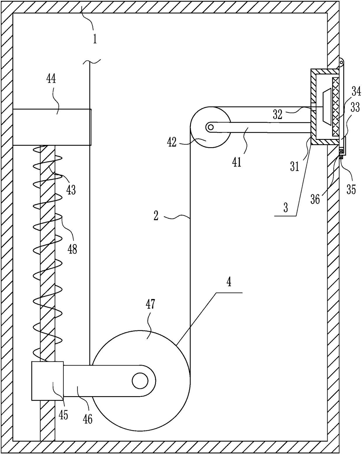
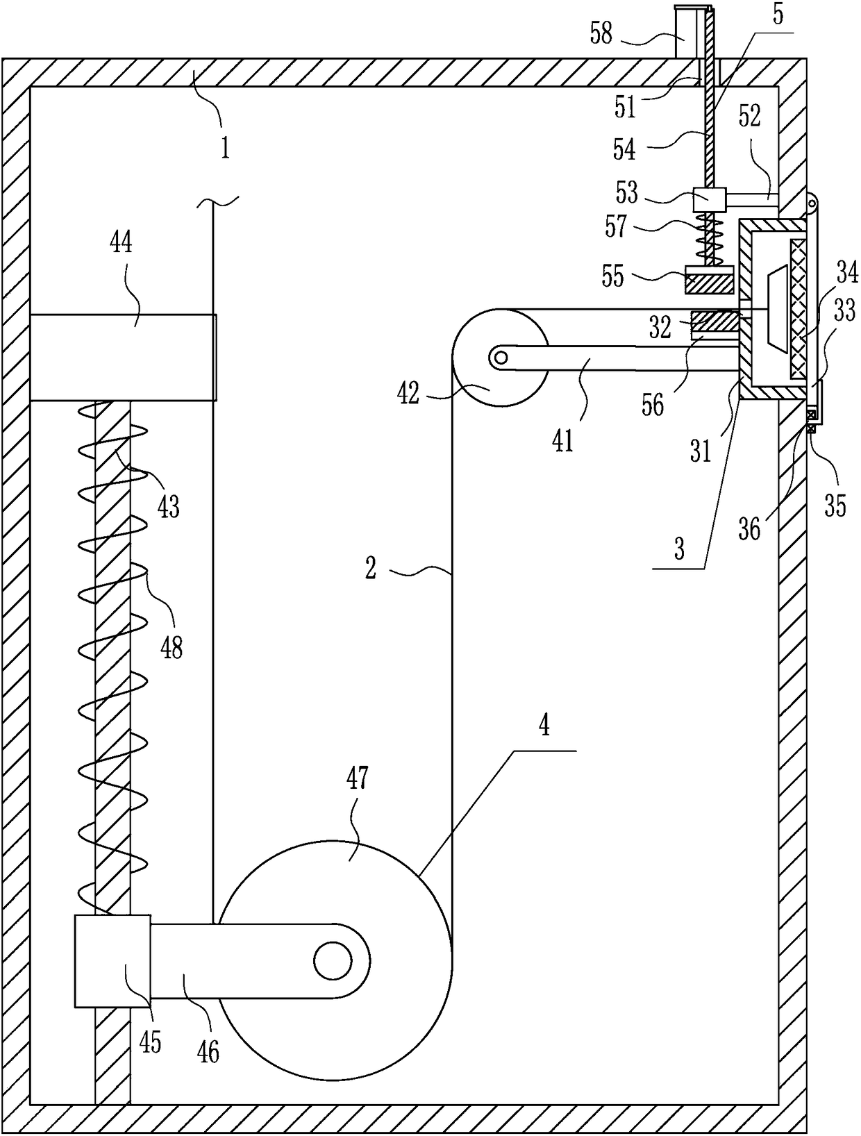
[0028] A retractable data transmission line for a switchgear, such as Figure 1-4 As shown, it includes a box body 1, a data transmission line 2, a sealing mechanism 3 and a take-up mechanism 4, a sealing mechanism 3 is provided on the upper right side of the box body 1, and a take-up line is provided between the sealing mechanism 3 and the left part of the box body 1. The mechanism 4, the data transmission line 2 is connected between the wire take-up mechanism 4 and the sealing mechanism 3, and the plug of the data transmission line 2 is located in the sealing device.

Embodiment 2

[0030] A retractable data transmission line for a switchgear, such as Figure 1-4 As shown, it includes a box body 1, a data transmission line 2, a sealing mechanism 3 and a take-up mechanism 4, a sealing mechanism 3 is provided on the upper right side of the box body 1, and a take-up line is provided between the sealing mechanism 3 and the left part of the box body 1. The mechanism 4, the data transmission line 2 is connected between the wire take-up mechanism 4 and the sealing mechanism 3, and the plug of the data transmission line 2 is located in the sealing device.

[0031] The sealing mechanism 3 includes a frame body 31, a cover plate 33, a sponge block 34, a first bearing seat 35 and a first 7-type rotating rod 36, and a frame body 31 is embedded in the upper part of the right side of the box body 1, and the frame body 31 left There is a wire hole 32 in the middle part of the side, the data transmission line 2 is located in the wire hole 32, the plug of the data transmi...

Embodiment 3

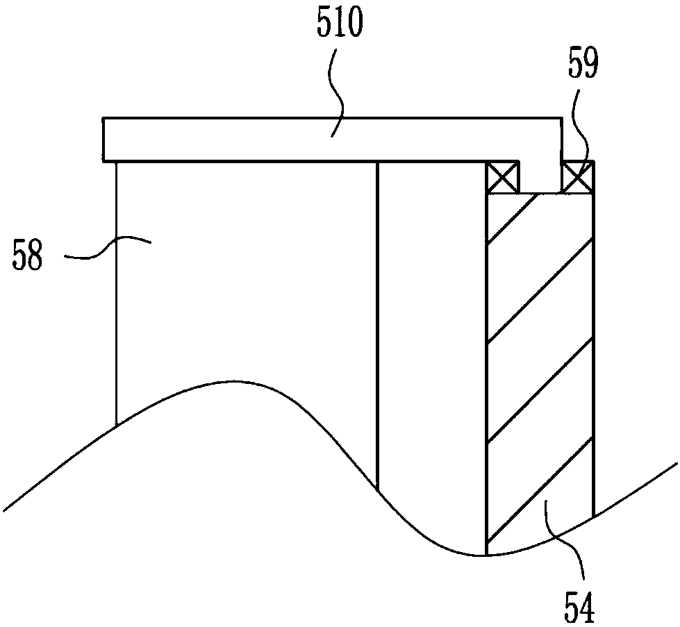
[0033] A retractable data transmission line for a switchgear, such as Figure 1-4 As shown, it includes a box body 1, a data transmission line 2, a sealing mechanism 3 and a take-up mechanism 4, a sealing mechanism 3 is provided on the upper right side of the box body 1, and a take-up line is provided between the sealing mechanism 3 and the left part of the box body 1. The mechanism 4, the data transmission line 2 is connected between the wire take-up mechanism 4 and the sealing mechanism 3, and the plug of the data transmission line 2 is located in the sealing device.

[0034] The sealing mechanism 3 includes a frame body 31, a cover plate 33, a sponge block 34, a first bearing seat 35 and a first 7-type rotating rod 36, and a frame body 31 is embedded in the upper part of the right side of the box body 1, and the frame body 31 left There is a wire hole 32 in the middle part of the side, the data transmission line 2 is located in the wire hole 32, the plug of the data transmi...


PUM


Abstract

The invention relates to a data transmission line, more particularly to an extension type data transmission line for a switch cabinet. The extension type data transmission line can be contracted or stretched and can be used and carried conveniently; and when the line is in use, a phenomenon that detection of the switch cabinet is affected when people kicks the data transmission line easily is avoided. The extension type data transmission line comprises a box body and the like. A sealing mechanism is arranged at the upper right side of the box body; a take-up mechanism is arranged between the sealing mechanism and the left part of the inside of the box body; a data transmission line is connected between the take-up mechanism and the sealing mechanism; and a plug of the data transmission line is located in the sealing mechanism. With a fixation mechanism, the data transmission line in use can be fixed well and a phenomenon that detection of the switch cabinet is affected due to movementof the data transmission line is prevented; the extension type data transmission line can be contracted or stretched and can be used and carried conveniently; and a phenomenon that detection of the switch cabinet is affected when people kicks the data transmission line easily is avoided.

Description

technical field [0001] The invention relates to a data transmission line, in particular to a scalable data transmission line for a switch cabinet. Background technique [0002] The switch cabinet is a kind of electrical equipment. The outside line of the switch cabinet first enters the main control switch in the cabinet, and then enters the sub-control switch. Each branch is set according to its needs. Such as instruments, automatic controls, motor magnetic switches, various AC contactors, etc., some also have high-voltage room and low-voltage room switch cabinets, high-voltage busbars, such as power plants, etc. load shedding. [0003] The switchgear needs to be tested regularly, and the data transmission line is needed for detection, and the general data transmission line is very long, which is not convenient to carry, and it is easy to be kicked by people passing by when using it. For the detection of switch cabinets, it is urgent to develop a scalable data transmission...

Claims


Application Information

Patent Timeline
IPC IPC(8): H01R13/72H01R13/52H01R13/502
Inventor 龙延华陈泽弘涂文
Owner JIANGSU HAITONG ELECTRICAL APPLIANCE CO LTD
Learn More